background image

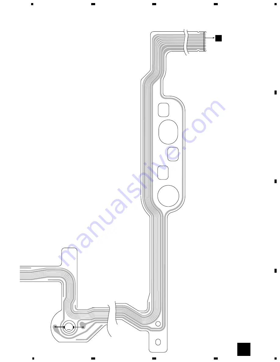
M

M4

CARRIAGE

1

12

D

CN301

35

CDX-MG6346ZH,MG6446ZH

5

6

7

8

5

6

7

8

D

C

B

A

E

C

Содержание CDX-MG6056ZH

Страница 1: ...l s Model No Order No Mech Module Remarks CDX MG6346ZH ES CRT2407 CX 890 CRT2376 G1 CD Mech Module Circuit Description Mech Description Disassembly EXPLODED VIEWS AND PARTS LIST PACKING Page 3 PACKING SECTION PARTS LIST Part No Mark No Symbol and Description CDX MG6346ZH ES CDX MG6056ZH UC 5 Owner s Manual CRB1744 CRB1627 English 11 Carton CHG4457 CHG4212 12 Contain Box CHL4457 CHL4212 Protector C...

Страница 2: ... 3 BLOCK DIAGRAM AND SCHEMATIC DIAGRAM 10 4 PCB CONNECTION DIAGRAM 26 5 ELECTRICAL PARTS LIST 42 6 ADJUSTMENT 46 7 GENERAL INFORMATION 48 7 1 DIAGNOSIS 48 7 1 1 TEST MODE 48 7 1 2 DISASSEMBLY 52 7 1 3 CONNECTOR FUNCTION DESCRIPTION 56 7 2 IC 57 8 OPERATIONS AND SPECIFICATIONS 61 VEHICLE DESTINATION PRODUCED AFTER HONDA PART No ID No PIONEER MODEL No Not specified THAILAND AUSTRALIA October 1999 08...

Страница 3: ...n 2 As the ACC is turned on the disc indicator blinks in red 3 When the blinking is stopped the mechanism is ready for the transportation 4 Attach the Transportation Bracket CNC7878 Now you can transport it See the figure below This service manual is intended for qualified service technicians it is not meant for the casual do it yourselfer Qualified technicians have the necessary test equipment an...

Страница 4: ...2124 11 Carton CDX MG6346ZH ES CHG3909 Carton CDX MG6446ZH ES CHG3991 12 Contain Box CDX MG6346ZH ES CHL3909 Contain Box CDX MG6446ZH ES CHL3991 13 Band CNF 512 Mark No Description Part No Mark No Description Part No PACKING SECTION PARTS LIST NOTE Parts marked by are generally unavailable because they are not in our Master Spare Parts List Screws adjacent to mark on the product are used for disas...

Страница 5: ...4 CDX MG6346ZH MG6446ZH 2 2 EXTERIOR ...

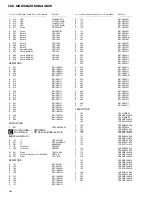
Страница 6: ... CAC5864 26 Button CAC5865 27 Door CAT2003 28 Washer CBF1038 29 Spring CBH2201 30 Spring CBH2200 31 Conductor CNC8051 32 Lighting Conductor CNV5901 33 Gear CNV5547 34 Arm CNV5548 35 Guide CNV5880 36 Sheet CNM6318 37 Double Faced Tape CNM6424 38 Insulator CNM6512 39 PCB CNP5373 40 Bracket Unit CXB3111 41 Grille Unit CXB3409 42 Screw IMS20P040FMC 43 CD Mechanism Module G1 CXK4702 44 Screw IMS20P040F...

Страница 7: ...6 CDX MG6346ZH MG6446ZH 2 3 CD MECHANISM ...

Страница 8: ...oller CLA3159 48 Roller CLA3160 49 Shaft CLA3179 50 Spacer CLA3194 51 Roller CLA3248 52 Bush CLA3353 53 Shaft CLA3469 54 Shaft CLA3693 55 Steer CNC7215 56 Steer CNC7216 57 Cam CNC7227 58 Holder CNC7235 59 Gear CNC7236 60 Gear CNC7238 61 Lever CNC7243 62 Lever CNC7244 63 Lever CNC7245 64 Lever CNC7246 65 Cover CNC7441 66 Holder CNC8613 67 Lever CNC8024 68 Gear CNC8140 69 Sheet CNM5831 70 PCB CNP568...

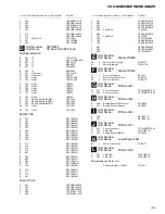
Страница 9: ... Unit CXB4450 141 Insulator CNM6306 142 Spacer CNM6345 143 Motor M5 SPINDLE CXM1120 144 Screw JFZ14P020FZK 145 Washer YE15FUC 146 Arm Unit CXB4953 147 Arm Unit CXB4954 148 Tray Assy CXB4307 149 Spring CBH2269 150 Sheet CNM6699 151 Cam Motor Assy CXB3170 152 Spacer CNC8289 153 Bracket Unit CXB4165 154 Motor Unit M1 Cam Gear CXB3174 155 Motor Unit M3 ELV CXB3175 156 Screw JFZ20P025FMC 157 Loading Ar...

Страница 10: ...L202IRXTU 190 Switch S887 CLAMP CSN1051 191 Switch S886 ELV HOME CSN1052 192 Bracket Unit CXB4306 193 Photo transistor Q851 852 CPT230SCTD CD 194 Resistor R856 RS1 8S911J 195 Resistor R857 RS1 8S821J 196 Photo interrupter Q1 RPI 221 197 198 Pickup Unit Service P8 CXX1311 ...

Страница 11: ... B DA LR X IC502 MSM514400DP 60TS 4M DRAM V 5V IC701 BA05S 5V REGULA VM 4 1 XAO XSTB XSO XS MOTOR DRIVER IC802 LB1836M 2 6 3 5 ELVSNS MOTOR DRIVER LB1836M IC801 2 6 13 9 5 3 12 10 CG CG EL EL PVD LO LO PVD PVD Q80 Q802 CLAMP ELHOME CN802 M BCL SPINDLE MOTOR CARRIAGE MOTOR HOME SWITCH EC VM VCC ST SR GND HOME M LOADING MOTOR M CAMGEAR MOTOR M ELEVATION MOTOR Q851 Q852 D891 D892 PH1 PVD Q881 D883 PH...

Страница 12: ...4 CD LCH BUS ASENS VDCONT Q751 Q754 X601 Q701 Q702 SWDACC NHOUT NHPOW Q753 XOUT XIN BSENS ASENS CDMUTE VDCONT CONT EMPH EXMODE POWER LOADSW DOORSW ELVSW CG1 CG2 ELV1 ELV2 LO1 LO2 PH3 PH2 PH1 LOAD ELHOME CLAMPSW 26 79 17 2 18 62 61 60 59 58 57 78 77 76 55 6 5 DCLOSE EJECTKEY ILL1 ILL2 ILPOW EXSO EXCSK DATA EXCK 40 14 36 37 70 68 66 67 Q741 Q733 Q732 B U Q731 Q734 Q742 GND CN701 CN901 CN103 KEY DATA...

Страница 13: ...RALL CONNECTION DIAGRAM GUIDE PAGE Note When ordering service parts be sure to refer to EXPLODED VIEWS AND PARTS LIST or ELECTRICAL PARTS LIST A a A b A a A b A b A a Large size SCH diagram Guide page Detailed page B A a D CD CORE UNIT STS UNIT B KEYBOARD UNIT ...

Страница 14: ...13 CDX MG6346ZH MG6446ZH 5 6 7 8 5 6 7 8 D C B A A A b A EXTENSION UNIT ...

Страница 15: ...14 CDX MG6346ZH MG6446ZH 1 2 3 4 1 2 3 4 D C B A 1 A a A b D CD CORE UNIT STS UNIT A a ...

Страница 16: ...15 CDX MG6346ZH MG6446ZH 5 6 7 8 5 6 7 8 D C B A A a A b B 2 B KEYBOARD UNIT A a ...

Страница 17: ...16 CDX MG6346ZH MG6446ZH 1 2 3 4 1 2 3 4 D C B A A a A b 1 A EXTENSION UNIT A b ...

Страница 18: ...17 CDX MG6346ZH MG6446ZH 5 6 7 8 5 6 7 8 D C B A A a A b 2 A b ...

Страница 19: ...INDLE CXM1120 DISC INSERT DETECT M4 CARRIAGE CXB3178 2 5V RF AMP AUTO POWER CONTROL CD DRIVER D E MOTOR PCB B CD CORE UNIT SERVO UNIT 18 CDX MG6346ZH MG6446ZH 1 2 3 4 1 2 3 4 D C B A C E C 3 2 CD CORE UNIT SERVO UNIT ...

Страница 20: ...16 934MHz 22 6R3 FOCUS TRACKING CARRIAGE SPINDLE DIGITAL SERVO DIGITAL SIGNAL PROCESSOR D A CONVERTER F 19 CDX MG6346ZH MG6446ZH 5 6 7 8 5 6 7 8 D C B A C ...

Страница 21: ... MEMORY CONTRO 5V REGULATOR 7 5V 9 0V MOTOR DRIVER G F D H LOAD SWITCH DOOR SWITCH MODE SWITCH CD CORE UNIT STS UNIT CD CORE UNIT SERVO UNIT MOTOR PCB A ELV SENSE 20 CDX MG6346ZH MG6446ZH 1 2 3 4 1 2 3 4 D C B A D F C D 3 3 CD CORE UNIT STS UNIT ...

Страница 22: ...22 6R3 TRACK RY CONTROLLER RIVER MOTOR DRIVER 4M DRAM D A CONVERTER A CN101 21 CDX MG6346ZH MG6446ZH 5 6 7 8 5 6 7 8 D C B A D ...

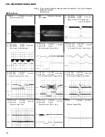
Страница 23: ...s div 8 CH1 TEY 0 5V div 9 CH2 TIN 0 5V div Test mode 32 tracks jump FWD 0 5ms div 8 CH1 TEY 0 5V div 9 CH2 TIN 0 5V div Test mode Single jump FWD 0 5ms div 6 CH1 FEY 0 1V div 3 CH2 FIN 0 2V div Normal mode Play 20ms div 3 CH1 FIN 0 5V div 0 CH2 SIN 1V div Normal mode Focus close 0 5s div GND GND GND GND Waveforms 0 SIN 0 5V div 0 1s div Normal mode Play REFOUT REFOUT REFOUT REFOUT REFOUT REFOUT R...

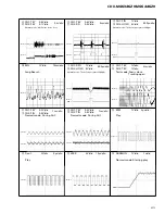
Страница 24: ...g open 2ms div 6 CH1 FEY 0 2V div 3 CH2 FIN 0 5V div Normal mode During AGC 1ms div EFM 1V div 2µs div Play 0 2s div Dout 2V div 5µs div Play LRCK 2V div 10µs div ADRMON 1V div 1s div Normal mode Starting play GND REFOUT REFOUT REFOUT REFOUT REFOUT REFOUT REFOUT REFOUT REFOUT REFOUT REFOUT REFOUT REFOUT REFOUT 1 CH1 RFO 1V div CH2 HOLD 5V div Normal mode The defect part passes 800µm 500µs div REFO...

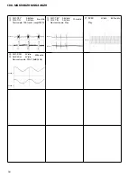
Страница 25: ...IN 0 5V div Test mode 100 tracks jump FWD 8 CH1 TEY 0 5V div 9 CH2 TIN 0 5V div Normal mode Play 10ms div 5ms div REFOUT REFOUT SCKO 2V div 500ns div Play REFOUT CH1 RCH 2V div CH2 LCH 2V div Normal mode PLAY 0dB 1kHz 200µs div AAGND AAGND REFOUT REFOUT ...

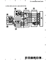
Страница 26: ...77 G CN802 SWITCH PCB UNIT A PCB UNIT C PCB UNIT E PCB UNIT B PCB UNIT D LOAD MOTOR PCB CPT230SCTD CD CPT230SCTD CD 25 CDX MG6346ZH MG6446ZH 1 2 3 4 1 2 3 4 D C B A 3 4 PCB UNIT A B C D E LOAD MOTOR PCB L I H G J K G D ...

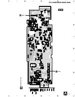
Страница 27: ...include all necessary parts for several destination For further information for respective destinations be sure to check with the schematic dia gram 2 Viewpoint of PCB diagrams EXTENSION UNIT 4 PCB CONNECTION DIAGRAM 4 1 EXTENSION UNIT Capacitor Connector P C Board Chip Part SIDE A SIDE B SIDE A CORD A A ...

Страница 28: ...27 CDX MG6346ZH MG6446ZH 1 2 3 4 1 2 3 4 D C B A CN701 CN901 EXTENSION UNIT SIDE B A A B D ...

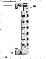
Страница 29: ...28 CDX MG6346ZH MG6446ZH 1 2 3 4 1 2 3 4 D C B A 4 2 KEYBOARD UNIT KEYBOARD UNIT CN701 SIDE A B B A ...

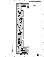
Страница 30: ...29 CDX MG6346ZH MG6446ZH 1 2 3 4 1 2 3 4 D C B A SIDE B KEYBOARD UNIT B B ...

Страница 31: ...30 CDX MG6346ZH MG6446ZH 1 2 3 4 1 2 3 4 D C B A 4 3 CD CORE UNIT SERVO UNIT CD CORE UNIT SERVO UNIT SIDE A C E C F PICKUP UNIT SERVICE ...

Страница 32: ...31 CDX MG6346ZH MG6446ZH 1 2 3 4 1 2 3 4 D C B A CD CORE UNIT SERVO UNIT SIDE B C C ...

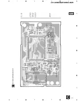
Страница 33: ...32 CDX MG6346ZH MG6446ZH 1 2 3 4 1 2 3 4 D C B A 4 4 CD CORE UNIT STS UNIT CN101 SIDE A D A F H D CD CORE UNIT STS UNIT ...

Страница 34: ...33 CDX MG6346ZH MG6446ZH 1 2 3 4 1 2 3 4 D C B A CD CORE UNIT STS UNIT SIDE B D D ...

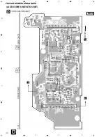
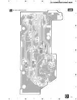
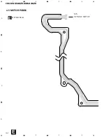
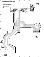
Страница 35: ...34 CDX MG6346ZH MG6446ZH 1 2 3 4 1 2 3 4 D C B A 4 5 MOTOR PCB B MOTOR PCB B E E SPINDLE MOTOR M5 ...

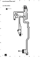
Страница 36: ...M M4 CARRIAGE 1 12 D CN301 35 CDX MG6346ZH MG6446ZH 5 6 7 8 5 6 7 8 D C B A E C ...

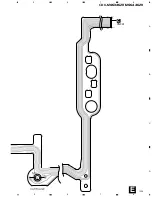
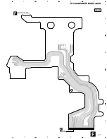
Страница 37: ...M M3 ELV M M1 CAM GEAR Q1 ELV SENSE 1 30 D CN201 36 CDX MG6346ZH MG6446ZH 1 2 3 4 1 2 3 4 D C B A 4 6 MOTOR PCB A MOTOR PCB A F SIDE A C F ...

Страница 38: ...1 41 G CN801 37 CDX MG6346ZH MG6446ZH 1 2 3 4 1 2 3 4 D C B A MOTOR PCB A F SIDE B F D ...

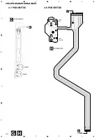
Страница 39: ...S887 CLAMP 1 11 1 7 S886 ELV G CN802 I 38 CDX MG6346ZH MG6446ZH 1 2 3 4 1 2 3 4 D C B A 4 8 PCB UNIT B PCB UNIT B 4 7 PCB UNIT D PCB UNIT D G H G H D ...

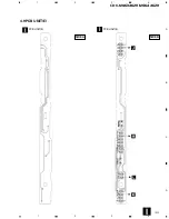
Страница 40: ...39 CDX MG6346ZH MG6446ZH 1 2 3 4 1 2 3 4 D C B A 4 9 PCB UNIT E PCB UNIT E PCB UNIT E SIDE A SIDE B I I I ...

Страница 41: ...1 4 D883 S885 MAX DETECT Q881 40 CDX MG6346ZH MG6446ZH 1 2 3 4 1 2 3 4 D C B A 4 10 PCB UNIT C PCB UNIT C J J I ...

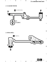
Страница 42: ...M M2 LOADING 1 1 4 2 I M D891 D892 1 2 41 CDX MG6346ZH MG6446ZH 1 2 3 4 1 2 3 4 D C B A 4 11 LOAD MOTOR PCB 4 12 PCB UNIT A LOAD MOTOR PCB PCB UNIT A K L K L G I I ...

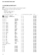
Страница 43: ...53J R 110 RS1 16S822J R 111 RS1 16S822J R 112 RS1 16S153J R 113 RS1 16S104J R 114 RS1 16S104J R 115 RS1 16S104J R 116 RS1 16S104J R 117 RS1 16S221J R 118 RS1 16S221J R 119 RS1 16S221J R 120 RS1 16S221J R 121 RS1 16S103J R 501 RS1 8S101J R 502 RS1 8S101J R 601 RS1 16S473J R 602 RS1 16S473J R 603 RS1 16S473J R 604 RS1 16S102J R 605 RS1 16S222J R 606 RS1 16S222J R 607 RS1 16S222J R 608 RS1 16S222J R ...

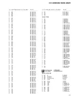
Страница 44: ...752 RS1 16S473J R 753 RS1 10S223J R 754 RS1 16S101J R 755 RS1 4S221J R 756 RS1 16S681J R 757 RS1 16S511J R 758 RS1 16S561J R 759 RS1 16S103J R 760 RS1 16S273J CAPACITORS C 101 CEV4R7M35 C 102 CEV4R7M35 C 103 CEV4R7M35 C 104 CEV4R7M35 C 105 CCSRCH101J50 C 106 CCSRCH101J50 C 107 CCSRCH101J50 C 108 CCSRCH101J50 C 109 CKSRYB473K16 C 110 CKSRYB473K16 C 111 CEV4R7M35 C 112 CEV4R7M35 C 113 CEV4R7M35 C 11...

Страница 45: ...106 RS1 16S183J R 107 RS1 16S822J R 108 RS1 16S333J R 109 RS1 16S683J R 110 RS1 16S134J R 111 RS1 16S273J R 112 RS1 16S222J R 113 RS1 16S103J R 114 RS1 16S103J R 115 RS1 16S102J R 116 RS1 16S163J R 117 RS1 16S163J R 120 RS1 16S101J R 121 RS1 16S101J R 125 RS1 16S0R0J R 201 RS1 16S104J R 202 RS1 16S103J R 203 RS1 16S332J R 204 RS1 16S752J R 205 RS1 16S752J R 206 RS1 16S101J R 250 RS1 16S331J R 251 ...

Страница 46: ...J R 717 RS1 16S471J R 718 RS1 16S471J R 801 RS1 10S102J CAPACITORS C 501 CKSQYB334K16 C 502 CKSQYB334K16 C 503 CKSQYB334K16 C 504 CCSRCH471J50 C 506 CCSRCH221J50 C 601 CKSQYB334K16 C 602 CCSRCH221J50 C 603 CKSQYB334K16 C 604 CKSQYB334K16 C 605 22µF 6 3V CCH1300 C 606 CKSQYB334K16 C 701 22µF 6 3V CCH1300 C 702 CEVL101M6R3 C 703 CKSQYB334K16 C 704 CKSQYB334K16 C 801 CKSQYB104K25 C 802 CKSQYB104K25 C...

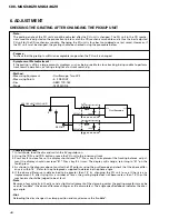
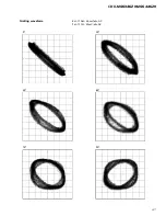
Страница 47: ...gulator on 2 Using the TRK and TRK buttons move the PU unit to the innermost track 3 Press key 3 to close focus the display should read 91 Press key 2 to implement the tracking balance adjust ment the display should now read 81 Press key 3 4 times The display will change returning to 81 on the fourth press 4 As shown in the diagram above monitor the LPF outputs using the oscilloscope and check tha...

Страница 48: ...47 CDX MG6346ZH MG6446ZH Grating waveform Ech Xch 20mV div AC Fch Ych 20mV div AC 45 0 75 60 30 90 ...

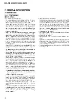
Страница 49: ...ploys a photo transistor for detecting discs at their loading or ejection Thus if its outer case is removed during repair work and internal parts are exposed to light of strong intensity malfunctions including the following can result The eject button becomes inoperable during play Pressing the eject button does not eject a disc and play is continued Loading becomes unavailable If a malfunction is...

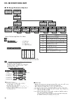
Страница 50: ... Single TR 91 When ACC or Back up is off the test mode is canceled Note Note Note The GA NET BUS head unit made by Pioneer must be employed for controlling the test mode Sound is unavailable even after the tracking has been closed this trouble results when the IC for the STS is not controlled in the test mode When you pressed the TRK or TRK key during the Focus Search you must turn the power off i...

Страница 51: ...0 1 2 3 4 5 6 7 L H Phototransistor is OPEN and switch is ON Phototransistor is CLOSE and switch is OFF SEC 1 When ELV motor is selected ELV position is displayed 01 ELV at home position 1st disc 10 ELV at a position other than home 2nd to 6th 11 ELV moving to a specified position Note 1 00 Reserved for an error 2 When CAM LOAD motor is selected Indicates CAMSW CAM gear status EJECT SW1 DOORSW SW2...

Страница 52: ... The next display of 10 tells you the elevation of the 3rd disc Repeating this operation allows you to establish an elevation matching each disc When the elevation is driven from the 1st through 6th disc the status display changes as 01 11 10 11 10 11 10 11 10 11 10 When the disc to be ejected coincides with the disc being clamped the above operations are not necessary Select the 1 CAM MOTOR and t...

Страница 53: ...holder 3 Remove the two spring As spring B and spring C from the hook then remove the CD mecha nism module Removing the Keyboard Unit Fig 3 1 Remove the screws A and four screws B then remove the keyboard unit 2 Remove the four screws C then remove the guide Precautions on Assembly Apply spring C black to the front side hook Remaining springs A and B are to be hung on the center hook Fig 1 Fig 2 F...

Страница 54: ... and CN301 4 Remove the Tray holder and the Tray assy See above 5 Rotate the Cam gear motor until the positions of all holes E match then stop the motor The Carriage Mech assy will stop as shown in the Fig 7 When the positions of all holes match they will be completely covered by the Carriage mech assy To rotate the Cam Gear motor see How to remove the Tray assy 6 Unhook the spring A 7 Remove the ...

Страница 55: ...ver by sliding it 4 Remove the feed screw pressure spring D 5 Loosen the 2 screws Remove the feed screw holder E 6 Remove the belt 7 Remove the Pickup unit together with the feed screw Be careful not to lose the shaft holders at the both ends of the feed screw Be careful not to damage the 2 flexible PCBs for the Pickup and motor when separating them The flexi ble PCBs have been stuck each other wi...

Страница 56: ...6446ZH 8 Loosen the 2 screws Remove the plate spring and the rack 9 Pull out the feed screw from the Pickup unit Rack Plate spring Feed screw Pickup unit Grease White KD 1 Grease Yellow PG 641 Fig 10 Grease Yellow PG 641 ...

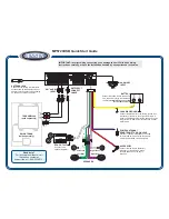
Страница 57: ...56 CDX MG6346ZH MG6446ZH 7 1 3 CONNECTOR FUNCTION DESCRIPTION 14 13 12 11 10 9 8 7 6 5 4 3 2 1 1 Lch 2 Rch 3 AGND 4 GND 5 SWDACC 6 B UP 7 Lch 8 Rch 9 NC 10 BUS GND 11 BUS 12 BUS 13 ILL 14 NC ...

Страница 58: ...control output 28 XIN I Crystal oscillating element connection pin 29 XOUT O Crystal oscillating element connection pin 30 VSS GND 31 33 KST1 3 O Key strobe output 34 35 kd I Key data input 36 37 ILL1 2 O Illumination output 38 ASCON O Analog switch control output 39 testin I Test program mode input 40 DCLOSE I Door close sense input 41 WDSL O Data comparison designation output 42 XWIH I DRAM data...

Страница 59: ... D converter reference voltage input 76 78 PH1 3 I Disc photo sense input 79 ELVSNS I ELV position sense input 80 TEMP I Temperature detector input 80 1 20 21 40 41 60 61 PD5540A IC s marked by are MOS type Be careful in handling them because they are very liable to be damaged by electrostatic induction 20 19 18 17 VDD oe Q11 Q10 16 15 14 13 Q9 Q8 Q7 NC 12 11 NC Q6 1 2 3 4 VSS DATA CLOCK LCK 5 6 7...

Страница 60: ...resh Control Clock Sense Amplifiers I O Selector Output Buffers Input Buffers Row Address Buffers Row Decoders Word Drivers Memory Cells On Chip Vbb Generater 10 10 10 10 4 4 4 4 4 4 4 28 27 26 25 PreVcc OPIN4 OPIN4 OPOUT4 24 23 22 OPIN3 OPIN3 OPOUT3 21 20 19 18 GND STBY PowVcc VO3 17 16 15 VO3 VO4 VO4 1 2 3 4 BIAS IN OPIN1 OPIN1 OPOUT1 5 6 7 OPIN2 OPIN2 OPOUT2 8 9 10 11 GND MUTE PowVcc VO2 12 13 ...

Страница 61: ...RCK WDCK WDCI LRCI 31 32 BCKI DATI 48 47 46 45 XOE XCAS D3 D2 44 43 42 41 D0 MCSL C176 VSS 40 39 XTLI D1 38 37 36 35 XTLO OSCE NC MCK 34 33 RFCK XROI 64 63 62 61 XEMP XWIH NC A4 60 59 58 57 A6 A7 A8 VDD 56 55 A3 A5 54 53 52 51 A2 A1 A0 A9 50 49 XWE XRAS Timing controller CPU interface VWA register CK generator WA generator RA generator Remain area calcurator S P P S Status controller Data comparat...

Страница 62: ...ED flash es green and orange Green t Orange t Green t Orange If you do not load a CD within about 15 seconds the door will close Pressing the same disc number button again or press ing the eject button will cause the door to close LOADING THE CD con t Disc status LED 6 DISC IN DASH CD CHANGER CD Loading Slot 2 Notes Repeat steps and to load CDs in other disc numbers The unit may go into CD eject m...

Страница 63: ...Buttons 6 DISC IN DASH CD CHANGER Note If you do not remove the ejected CD from the CD loading slot within about 15 seconds it is automatically reloaded If you press the eject button or press the ejected CD s disc number button the Disc status LED that s flashing green the CD is immediately reloaded Note If you leave the ejected CD in the CD loading slot and press the disc number button for a CD t...

Страница 64: ...o system Usable discs Compact disc Signal format Sampling frequency 44 1 kHz Number of quantization bits 16 linear Frequency characteristics 5 20 000 Hz Signal to noise ratio 93 dB 1kHz IHF A network Dynamic range 92 dB 1kHz Number of channels 2 stereo ILLUMINATION 6 DISC IN DASH CD CHANGER Eject Button 3SEC 1 The illumination color changes each time you press and hold the eject button for 3 secon...

Страница 65: ...C PIONEER ELECTRONIC CORPORATION 1999 K ZZS FEB 1999 Printed in Japan ORDER NO CRT2376 CD MECHANISM MODULE CX 890 Service Manual CONTENTS 1 MAIN PARTS LOCATIONS 2 2 CIRCUIT DESCRIPTIONS 3 3 MECHANISM OPERATIONS 16 4 DISASSEMBLY 21 NOTE This Service Manual outlines operations of the CD mechanism module used in the models listed blow For repair use this Service Manual and the Service Manual of the m...

Страница 66: ... S803 Door switch S802 Load switch S801 Do not hold the upper frame of the disc insertion slot or the front side of the stage in the CD mechanism module when servicing to prevent them from being deformed CD Player Service Precautions 1 For pickup unit CXX1311 handling please refer to Disassembly Page 21 During replacement handling precautions shall be taken to prevent an electrostatic discharge pr...

Страница 67: ...9 28 27 26 25 24 23 22 21 20 X12 RF envelope AGC Detection X3 Phase detection 3T detection Bottom DC shift Peak Control DC shift Bottom Peak 120kΩ DEFECT circuit FE BAL FE BAL Vcc Mirror circuit FE BAL APC X2 Vcc FE BAL TE BAL ASY EFM OUT C DEF DEFECT RFOK MIRR 3T OUT C FE FE OUT FE GND TE TE OUT1 TE OUT2 DET IN DET OUT VREF IN VREF OUT LDON LD PD E F D B C A Vcc C2 3T C1 3T RF RF OUT RF IN C AGC ...

Страница 68: ... from Pin 35 As signal level amplification is 2 5 Vp p around REFOUT 4 DFCT defect circuit DFCT signal detects mirror defect in discs and is output from Pin 33 The system outputs H when a mirror defect is detected If disc is soiled the system determines it as lack of mir ror Therefore the system inputs the DFCT signal out put to the HOLD terminal of servo LSI Focus and track ing servo drives chang...

Страница 69: ...ting the zero cross point are as follows 1 To be used for counting tracks for carriage move and track jump 2 To be used for detecting the direction of lens move ment when tracking is closed To be used in the tracking brake circuit mentioned later The frequency range of TEC signal is from 500 Hz to 19 5 kHz Voltage TEC TE level x 4 In other words the TEC signal level is calculated as 6 Vp p This le...

Страница 70: ...uation signal from Pin 30 The resulting signal is obtained through L P F with a fc of 40 Hz This signal is used for automatic adjustment of FE bias MIRR COMP DC shift Peak AGC Bottom RFO Detection A 1 5V UPC2572GS Peak Bottom 4 31 RFIN B Z C RFO PEAK HOLD BOTTOM HOLD MIRROR 1 A 0 False MIRR caused by dirt True MIRR OFF TRACK Dirt etc B C Z Ø 3T OUT FE signal RFIN UPC2572GS C113 10nF FEY 3T detecti...

Страница 71: ...e and spindle are amplified in IC301 and BA5986FM and supplied to respective actuators and motors 1 Focus servo system The main equalizer of focus servo is located in the UPD63702AGF Fig 9 shows block diagram of the focus servo For the focus servo system the lens must be posi tioned within the focusing range in order to perform focus closing To achieve this the system moves the lens upward downwar...

Страница 72: ...cus closing The illustration shows when the system cannot perform focus closing S curve search voltage and actual lens behavior can be checked by pressing the Focus Close button when 01 is shown in Focus Mode Select in Test mode REFOUT FD LENS POSITION RELATIVE TO DISC NEAR FAR JUST FOCUSED SIN REFOUT Expanding around Just Focused Point REFOUT RFI FOK FEX FZD THRESHOLD LEVEL FZD INTERNAL SIGNAL Fo...

Страница 73: ...point of time when the set number is counted and stops the lens Thus track ing is closed and the system can continue normal play back To improve servo withdrawal during track jump the system sets the brake circuit to ON for 60 ms after brake pulse so that gain of the tracking servo can be increased FF REV in normal mode is made by continuously per forming single jump approximately ten times faster...

Страница 74: ...s the speed of the lens movement to stabilize withdrawal of the tracking servo The system judges sliding direction of track from TEC and MIRR signals as well as the relationship of their phase TEC TZC TEC SQUARED UP INTERNAL SIGNAL MIRR MIRR LATCHED AT TZC EDGES SWITCHING PULSE EQUALIZER OUTPUT SWITCHED DRIVE DIRECTION Note In the illustration the phase of equalizer output is shown as the same as ...

Страница 75: ...d level is set for equalizer output in the servo LSI and drive voltage is output from the servo LSI only when the equalizer out put level exceeds that level Thus power consumption is reduced Depending on eccentricity etc of disc the equalizer output voltage may cross the threshold level several times before the pickup unit as a whole starts operation At this time waveforms of drive voltage from LS...

Страница 76: ...ous status 4 Brake mode Mode to stop the spindle motor The microcomputer outputs brake voltage from the servo LSI Waveforms of EFM are monitored inside the LSI If the longest pattern of EFM exceeds speci fied intervals if the rotation speed adequately slowed down flag is activated in the LSI and the microcomputer turns brake voltage to OFF If no flag is activated after a specified time the microco...

Страница 77: ...6 pin name TBAL of the servo LSI 4 The voltage output from the servo LSI is input to Pin 37 of the preamplifier IC101 UPC2572GS Pin 37 is a control voltage terminal of the TEVCA amplifier According to voltage input the system changes gain of Ech and Fch in the preamplifier and adjusts the tracking balance to make the upper and lower por tions of TE waveforms symmetric to REFOUT 4 FE bias automatic...

Страница 78: ...n be displayed in Test mode for confirmation Display of coefficients in each automatic adjustment is as follows 1 FZD cancel TE OFST cancel T BAL and FE bias Reference 32 32 No adjustment was required Display is made in units of approximately 40 mV Example Coefficient of FZD cancel 35 35 32 3 3 x 40 mV 120 mV Corrected amount is approximately 120 mV Thus FE offset before adjustment is 120 mV 2 Adj...

Страница 79: ... 60TS and reads and outputs the data at normal speed in synchronization with the internally generated FS system clock In order to write the DA data at double speed and to read out at normal speed the DRAM becomes full but when it reaches capacity it will tenta tively stop reading data The CD is in the pause mode during this time When an available area is created by data read out from the DRAM data...

Страница 80: ...y position d The Cam gear rotates counterclockwise to move the LOAD arms as shown in Fig 21 e The LOAD arms push the disc loaded on the tray and open the tray hooks f When a disc is inserted the disc interrupts the infrared LED light from the photo transistors and the Rubber roller starts rotating The photo transistors are connected in serial When the light is interrupted from either photo transis...

Страница 81: ... 3 2 Elevation a The Cam gear rotates to the elevation OK position b The ELV motor rotates to slide the elevation lever via the gears c The 2 elevation levers left and right can synchronize their sliding via the joint arm d The shafts of the Stage Mech Assy engage with the stair like grooves in the elevation levers and the verti cal holes in the Main chassis via the rollers e When the elevation le...

Страница 82: ...p switch is turned ON Clamp UP lever Clamp arm Clamp UP roller Carriage Mech Assy Carriage drive shaft Carriage drive arm Clamp switch Fig 24 3 5 Disc Sense Initializing a The disc sense operation is to detect if or not a disc is loaded on the trays 1 to 6 b While a disc is inserted using the robber rollers the disc pushes the insertion completion switch via the arm to sense that a disc is loaded ...

Страница 83: ... as indi cated by the arrow in Fig 25 to push the mechanism forward and downward d The Mech lock lever left is driven by the movement of the Mech lock lever via the Mech lock junction lever to push the Mechanism downward e The mechanism lock is released only in the disc clamp mode Mech lock lever Mech lock lever left Mech lock junction lever Mech lock lever right Fig 25 Door switch Door lever Cam ...

Страница 84: ... the Stage lock lever right are pressed against the gear like portions of the chassis to lock the right side of the Stage mech assy d For the left side of the Stage mech assy in the mode described at the step d on 3 7 Mechanism lock the Mech lock junction lever is driven to move the Stage lock lever left e The 2 bent portions of the Stage lock lever left are pressed against the gear like portions ...

Страница 85: ...nd CN301 4 Remove the Tray holder and the Tray assy See above 5 Rotate the Cam gear motor until the positions of all holes E match then stop the motor The Carriage Mech assy will stop as shown in the Fig 30 When the positions of all holes match they will be completely covered by the Carriage mech assy To rotate the Cam Gear motor see How to remove the Tray assy 6 Unhook the spring A 7 Remove the f...

Страница 86: ...liding it 4 Remove the feed screw pressure spring D 5 Loosen the 2 screws Remove the feed screw holder E 6 Remove the belt 7 Remove the Pickup unit together with the feed screw Be careful not to lose the shaft holders at the both ends of the feed screw Be careful not to damage the 2 flexible PCBs for the Pickup and motor when separating them The flexi ble PCBs have been stuck each other with doubl...

Страница 87: ...e Cover from the Servo unit See Fig 30 Disconnect the flexible PCBs from the connectors CN101 and CN301 See Fig 30 2 Disconnect the the flexible PCB Motor PCB A from the connector CN201 on the Servo unit 3 Disconnect the flexible PCB from the connector CN801 on the STS unit 4 Loosen the 2 screws A Remove the Servo unit 5 Loosen the screw B Remove the flexible PCB hold er 6 De solder at the 4 porti...

Страница 88: ... the Cover from the Servo unit See Fig 30 Disconnect the flexible PCBs from the connectors CN101 and CN301 See Fig 30 Disconnect the the flexible PCB Motor PCB A from the connector CN201 on the Servo unit See Fig 36 2 Unhook the spring Remove the Door open lever 3 Loosen the 3 screws Remove the PCB units C D and the frame 4 Remove the spring A Gear cover Motor bracket assy Front Cam gear motor ELV...

Страница 89: ... 31 Remove the Servo unit See Fig 36 Remove the Motor PCB A See Fig 36 Remove the Gear cover Fig 37 2 Unhook the Spring C Remove the Door open lever 3 Loosen the screws D E and F Remove the PCB C and D and the frame 4 Unhook the springs A and B 5 Pull out the Load arm assy right upward 6 Unhook the spring G Remove the belt large 7 Loosen the screw H Remove the Load arm assy PCB E Loading motor Loa...

Страница 90: ...e the Mech lock junction lever and and roller D Pay attention to the mounting direction 14 Remove the 2 E shaped rings A and 2 washers B 15 Remove the Elevation lever right 16 Remove the 2 rollers C Pay attention to the mounting direction 17 Remove the Mech lock lever right 18 Lift up the Stage mech assy to remove it Motor bracket assy Photo interrupter Front Mech lock junction lever Elevation lev...

Отзывы: