Pioneer BDP-170 Скачать руководство пользователя страница 2

2

BDP-170

1

2

3

4

A

B

C

D

E

F

1

2

3

4

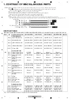
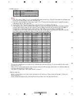
1. CONTRAST OF MISCELLANEOUS PARTS

CONTRAST TABLE

 BDP-160-K/YXE8, BDP-170/SXE, BDP-170/PWXE and BDP-80FD/CUXE are constructed the same except for the following:

 Notes : For PCB ASSEMBLIES, Refer to "CONTRAST OF PCB ASSEMBLIES".

Parts marked by "NSP" are generally unavailable because they are not in our Master Spare Parts List.
The       mark found on some component parts indicates the importance of the safety factor of the part.
Therefore, when replacing, be sure to use parts of identical designation.
Screws adjacent to     mark on product are used for disassembly.    
For the applying amount of lubricants or glue, follow the instructions in this manual.
(In the case of no amount instructions, apply as you think it appropriate.)
Nos. indicate the pages and Nos. in the service manual for the base model.

NOTES:

When ordering resistors, first convert  resistance values into code form as shown in the following examples.
Ex.1 When there are 2 effective digits (any digit apart from 0), such as 560 ohm and 47k ohm (tolerance is shown by J=5%,
            and K=10%).

Ex.2 When there are 3 effective digits (such as in high precision metal film resistors).

5 6 1
4 7 3

R 5 0

1 R 0

RD1/4PU            J
RN2H            K
RS1P            K

56 x 10

1

47 x 10

3


R50
1R0

561
473

RN1/4PC               F

562 x 10

1

5621

5

2

6

1

Mark

No.

Symbol and Description  BDP-160-K/YXE8

BDP-170/SXE

BDP-170/PWXE

BDP-80FD/CUXE Remarks
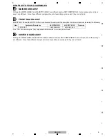
PCB ASSEMBLIES

P43-2 FRONT BOARD ASSY

08-BDP160-FV0

08-BDP170-FV0

08-BDP170-FV0

08-BDP170-FV0

P43-3 MAIN BOARD ASSY

08-BDP160-MA0/Y 08-BDP170-MA1/Y 08-BDP170-MA1/Y 08-BDP170-MA1/Y

P43-4 SWITCH BOARD ASSY

08-BDP160-SB0

08-BDP170-SB0

08-BDP170-SB0

08-BDP170-SB0

P43-6 POWER BOARD ASSY

08-P015BE-PW0

08-P015BE-PW0

08-P015BE-PW0

08-P015BE-PW2

P43-17 CD Door ASSY

08-BDP150-DA1

08-BDP150-DA1

08-BDP150-DA1

08-BDL170-DA0

PACKING SECTION

NSP

P41-1 Software License Notice

ARC8260

Not used

Not used

Not used

P41-1 Software License Notice

Not used

70-PONEER-LCSB2 70-PONEER-LCSB2 70-PONEER-LCSB2

P41-2 Remote Control Unit

 (RC-2426)

06-T2446E-A005

Not used

Not used

Not used

P41-2 Remote Control Unit

 (RC-2427)

Not used

Not used

Not used

06-T2446E-D004

P41-2 Remote Control Unit

 (RC-2429)

Not used

06-T2446E-D002

06-T2446E-D002

Not used

>

P41-3 AC Power Cord

51-DC0120-0CRA3 51-DC0120-0CRA3 51-JC0120-0PNC7 51-BC0150-0LSA9

P41-4 Operating Instructions

 (Fr/De/It/Nl/Es)

72-BDP160-EURB2

Not used

Not used

Not used

P41-5 Operating Instructions

 (En)

72-BDP160-GBRB2

Not used

72-BDP170-GBRB1

Not used

P41-5 Operating Instructions

 (Ru)

Not used

72-BDP170-RUSB1

Not used

Not used

P41-5 Operating Instructions

 (En/Fr/Es)

Not used

Not used

Not used

72-BDP170-USAB1

P41-7 Gift Box

76-104520-0ATE3

76-104520-0ATG7

76-104520-0ATG8

76-104520-0ATH3

P41-8 Right Card

76-104530-0AP-TL

Not used

Not used

Not used

P41-8 Front Paper Card

Not used

76-152590-0AP

76-152590-0AP

76-152590-0AP

P41-9 Left Card

76-104540-0AP-TL

Not used

Not used

Not used

P41-9 Back Paper Card

Not used

76-152580-0AP

76-152580-0AP

76-152580-0AP

EXTERIOR SECTION

P43-1 WIFI MODULE ASSY

07-WN713N-M1B

07-WM731N-M2B

07-WM731N-M2B

07-WM731N-M2B

P43-11 Tact Switch

48-TAC020-XX0

48-TAC041-XX0

48-TAC041-XX0

48-TAC041-XX0

P43-13 WiFi 4pin Cable

46-FF018F-04SA1

46-FF018F-04SC

46-FF018F-04SC

46-FF018F-04SC

P43-18 FRONT PANEL ASSY

08-BDP160-FA0

08-BDP170-FA1

08-BDP170-FA1

08-BDP170-FA4

P43-24 Rear Panel

67-BD15B1-1E0C1 67-BD15B1-1E0D5 67-BD15B1-1E0D6 67-BD15B1-1E0E3

Содержание BDP-170

Страница 1: ...apan BDP 170 RRV4572 Blu ray 3DTM PLAYER BDP 170 BDP 80FD THIS MANUAL IS APPLICABLE TO THE FOLLOWING MODEL S AND TYPE S This service manual should be used together with the following manual s For SPECIFICATIONS and PANEL FACILITIES refer to the operating instructions Model Type Power Requirement DVD Region No BD Region No Serial No Remarks BDP 170 SXE AC 110 V to 240 V 5 C UR UR RUSSIA BDP 170 PWX...

Страница 2: ... BDP170 SB0 08 BDP170 SB0 08 BDP170 SB0 P43 6 POWER BOARD ASSY 08 P015BE PW0 08 P015BE PW0 08 P015BE PW0 08 P015BE PW2 P43 17 CD Door ASSY 08 BDP150 DA1 08 BDP150 DA1 08 BDP150 DA1 08 BDL170 DA0 PACKING SECTION NSP P41 1 Software License Notice ARC8260 Not used Not used Not used P41 1 Software License Notice Not used 70 PONEER LCSB2 70 PONEER LCSB2 70 PONEER LCSB2 P41 2 Remote Control Unit RC 2426...

Страница 3: ... and 08 BDP170 FV0 are constructed the same with the exception of some components including the following Note This list is not complete Only components that are available as service part are listed CF SWITCH BOARD ASSY Although 08 BDP160 SB0 and 08 BDP170 SB0 are different and are NOT COMPATIBLE Some components on these assy s are different Since these different components are not available as se...

Страница 4: ... Wi Fi 4 pin cable is disconnected be sure to reconnect the cable so that the side on which the ferrite core is attached is connected to the MAIN BOARD Assy 3 When the Wi Fi 4 pin cable is to be replaced remove the ferrite core from the old cable then attach it to the new cable at a place approximately 30 mm away from the connector by wrapping the cable once around the ferrite core MAIN BOARD ASSY...

Страница 5: ...reen If it does not appear slowly press the number keys with a 1 second interval 1 Enter FA mode For the former model and will not be used to exchange this Loader 2 Save FE log to USB For Design and Development purposes and cannot be used for Service 3 Save FA result to USB For Design and Development purposes and cannot be used for Service 4 Laser Check Verifies laser diode Refer to Laser Check fo...

Страница 6: ...isplayed There are 17 items in the SP Mode the main items being for Production line and Design Development The following is to explain items usable in Service Other items require time for completion or are not suited for Service purposes If you select them by mistake press the STOP button to end that item you accidentally selected none of the items will affect the main unit 1 4 Laser Check Example...

Страница 7: ...by the disc If an NG is generated in other discs too the defect is likely to be caused by the drive part However even if Pass is displayed after this test it is difficult to determine that the Driver is normal with these Pass judgments only Tray Close Foucus ON TOC Read Tray Open 1 cycle 15 seconds x 20000 completed in approx 83 hours 20 minutes Can be implemented on all of CD DVD and BD Cannot ch...

Страница 8: ...be displayed on the FL display Note1 DVD and BD disc can be checked with Single Layer SL disc only If they are checked with Dual Layer DL disc an Error is generated The following serves as the Error List generated in SP MODE Error Code Error Name Description 12 PWR_CURVE_ERROR Power curve chk sum error 0x4E20 20000 Fifty times of random playback multiplied by 400 cycles equals 20 000 22 STARTUP_TI...

Страница 9: ...rom the Service Mode screen and press the ENTER button 3 After the measurement is started and completed the measurement value is displayed If the value is within the reference value Pass is displayed 4 Quit Service mode by pressing the STOP button The home menu screen will be displayed Note If you open the tray in this state then attempt to play a disc the Close indication is displayed on the FL d...

Страница 10: ...error rate will start 4 After error rate measurement is finished for the outermost track measurement will be stopped then the tray will automatically open For a DL disc measurement will be stopped after that for the outermost track of the first layer is finished then the tray will automatically open Note In Error Rate Measurement mode if the AC power cord is unplugged with the tray open the Error ...

Страница 11: ...values across discs or BD players used the results measured using the GGV1368 will not be completely the same Use these values just for reference For error rate measurement of an entire DL disc including that of the second layer it is recommended to measure the error rate using a PC When a PC is used for measurement measured error rate values will be graphed which makes this method suitable for er...

Страница 12: ...place the LOADER Assy Mechanical point Write barcode data for pickup adjustment Electric point When replace the LOADER Assy This time 2 When replace the MAIN BOARD Assy Mechanical point Read out barcode data for pickup adjustment Before replacing MAIN BOARD Assy Write barcode data for pickup adjustment After replacing MAIN BOARD Assy Electric point When replace the MAIN BOARD Assy About barcode da...

Страница 13: ...ase insert the USB memory device into unit While the screen shows the information that a USB memory device has been inserted please press HOME MENU button to enter the menu then find USB devices through Home Menu Initial Setup Options Update USB Storage After press the ENTER button the system will search the update file itself to update 4 After reset the unit is available for test 1 Plug a USB mem...

Страница 14: ...has been replaced Make sure that the USB memory device is recognized 5 Enter Service mode See HOW TO ENTER SERVICE MODE 6 Select 6 Repair Service then press the ENTER button 7 Select Write 2D barcode from USB memory then press the ENTER button 8 The message OK will be displayed on the screen when copying of the barcode data from the USB memory device is finished 9 Quit Service mode by pressing the...

Страница 15: ... Initial Setup then press the ENTER button 3 Move the cursor to Options then press the ENTER button Note In the case of the BDP 80FD after the MAIN BOARD Assy is replaced the frequency of the video output signals will become 50 Hz which may disable some TVs from displaying videos In such a case play back a BD disc for use in the U S A with 60 Hz video output stop playback then display the menu scr...

Страница 16: ...ayed Here an update file has been found Start update with version Press the ENTER button 7 After updating is completed the product will automatically restart After restarting is finished unplug the USB storage device 2 Changing the Destination Setting 1 Display the HOME MENU screen move the cursor to Initial Setup then press the ENTER button ...

Страница 17: ...supplied remote control unit 3 Select 9 Change Area at the bottom then press the ENTER button 4 As the destinations 0 to 8 are displayed select your region by moving the cursor then press the ENTER button 4 SXE Russia 5 PWXE Oceania 8 CUXE U S A 5 Turn the unit OFF then back ON again Be sure to do this after changing the destination setting ...

Страница 18: ...nation change has been successfully finished Tip It is recommended to confirm the region code at the same time 4 Press the HOME MENU button to return to the HOME MENU screen 4 Writing the Latest Firmware to the Product 1 Download the latest firmware for the product from the Website specially for service engineers to a USB storage device 2 Perform updating in the same manner as that described in 1 ...

Отзывы: