PSEN 4.2a/b/p/M12
Operating Manual PSEN 4.2a/b/p/M12 22188-EN-02
19
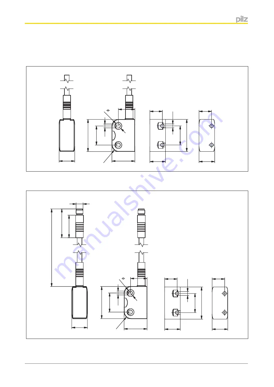
Dimensions in mm
PSEN cs4.2a, PSEN cs4.2b
18
R8
26,4
4,
5
22
37
8
14,4
PSEN cs4.2p
26
33
14
0
10
M
±
Страница 1: ...PSEN 4 2a b p M12 Operating Manual 22188 EN 02 PSEN sensor technology...
Страница 2: ...KG Copies may be made for internal purposes Suggestions and comments for improving this documentation will be gratefully received Pilz PIT PMI PNOZ Primo PSEN PSS PVIS SafetyBUS p SafetyEYE SafetyNET...
Страница 3: ...signment connector and cable 8 Connection to evaluation devices 8 Single connection 9 Series connection 10 Connection to PNOZ X PNOZpower PNOZsigma PNOZelog 11 Connection to PNOZmulti 13 Connection to...
Страница 4: ...t warns of a hazardous situation that poses an immediate threat of serious injury and death and indicates preventive measures that can be taken WARNING This warning must be heeded It warns of a hazard...
Страница 5: ...ble regulations for health and safety at work and accident prevention Ensure VDE and local regulations are met especially those relating to safety Any guarantee is rendered invalid if the housing is o...
Страница 6: ...nge Input S11 Input S21 Safety out put 12 Safety out put 22 Signal out put Y32 Yes High Low High Low High Yes Low High Low High High Yes High High High High High Yes Low Low Low Low High No x x Low Lo...
Страница 7: ...xis dependent on operating distances x axis Sao Assured operating distance 8 0 mm So Typical operating distance 11 0 mm Sr Typical release distance 14 0 mm Sar Assured release distance 20 0 mm Lateral...
Страница 8: ...on Wire colour 1 S21 Input channel 2 White 2 A1 24 VUB Brown 3 12 Output channel 1 Green 4 22 Output channel 2 Yellow 5 Y32 Signal output Grey 6 S11 Input channel 1 Pink 7 A2 0 V UB Blue 8 Do not conn...
Страница 9: ...PSEN 4 2a b p M12 Operating Manual PSEN 4 2a b p M12 22188 EN 02 9 Single connection Actuator Receiver Evaluation device...
Страница 10: ...AUTION Extension of delay on de energisation When several units are connected in series the delay on de energisation time increases in direct proportion to the number of interconnected safety switches...
Страница 11: ...N Only use safety relays with a 24 VDC supply voltage Safety relays with uni versal power supply or in AC unit versions have internal potential isolation and are not suitable as evaluation devices PNO...
Страница 12: ...PSEN 4 2a b p M12 Operating Manual PSEN 4 2a b p M12 22188 EN 02 12 PNOZ X2 9P PNOZ X10 1 PNOZ X10 11P PNOZ e1 1p PNOZ e1vp PNOZ e6 1p PNOZ e6vp PNOZ e5 11p PNOZ e5 13p...
Страница 13: ...actuator should be installed opposite each other in parallel CAUTION The unit s properties may be affected if installed in an environment contain ing electrically or magnetically conductive material P...
Страница 14: ...h in place 1 Do not fully tighten the 2nd screw on the safety switch 2 Attach the screws for the actuator leav ing a distance of 3 6 mm between the screw head and plate Slide the actuator on to the mo...
Страница 15: ...s on the actuator 4 Without UL approval 1 For UL approval Use the seals 2 to close the unused mounting holes on the actuator Use the seals 3 to close the mounting holes on the sensing face of the safe...
Страница 16: ...w head and plate For the next steps you will need the seals as illustrated Use the seals 2 to close the unused mounting holes on the actuator Slide the actuator on to the screws Align the actuator and...
Страница 17: ...operation Remedy Open both channels of the input circuit POWER Fault LED lights up red Error message Flashing codes for fault diagnostics are output to the Safety Gate and Input LEDs see Error displa...
Страница 18: ...At least one of the two safety out puts 12 and 22 have voltage ap plied during system run up Check the wiring of safety outputs 12 and 22 rectify the wiring error 1 12 3x short 1x long 12x long 3x sh...
Страница 19: ...ating Manual PSEN 4 2a b p M12 22188 EN 02 19 Dimensions in mm PSEN cs4 2a PSEN cs4 2b 18 19 R 8 26 4 4 5 22 37 8 18 37 22 4 5 14 4 18 14 4 PSEN cs4 2p 18 26 33 140 10 8 M 8 19 26 4 R 8 4 5 22 37 18 1...
Страница 20: ...2b General 541211 541212 Approvals CE GOST T V cULus Listed CE GOST T V cULus Listed Sensor s mode of operation Transponder Transponder Electrical data 541211 541212 Supply voltage Voltage 24 V 24 V...
Страница 21: ...safety outputs 2 2 Signal outputs 1 1 Potential isolation from system volt age No No Short circuit proof Yes Yes Times 541211 541212 Test pulse duration safety outputs 450 s 450 s Switch on delay Aft...
Страница 22: ...e 0 80 kV 0 80 kV Protection type Housing IP6K9K IP6K9K Mechanical data 541211 541212 Change of switching distance with fluctions in temperature 0 01mm C 0 01mm C Actuator 1 PSEN cs4 1 PSEN cs4 1 Typ...
Страница 23: ...cts 400 nF 400 nF PNOZmulti PNOZelog PSS 400 nF 400 nF Max inrush current impulse Current pulse A1 0 58 A 0 58 A Pulse duration A1 1 0000 ms 1 0000 ms Max overall cable resistance Rl max Single channe...
Страница 24: ...3 r h at 40 C EMC EN 60947 5 3 EN 60947 5 3 Vibration In accordance with the standard EN 60947 5 2 EN 60947 5 2 Frequency 10 0 55 0 Hz 10 0 55 0 Hz Amplitude 1 00 mm 1 00 mm Shock stress In accordance...
Страница 25: ...g Weight 50 g 45 g The standards current on 2009 01 apply Safety characteristic data Operating mode EN ISO 13849 1 2008 PL EN ISO 13849 1 2008 Category EN IEC 62061 SIL CL EN IEC 62061 PFHD 1 h IEC 6...
Страница 26: ...ector 541 210 PSEN cs4 2a PSEN cs4 1 Safety gate system uniquely coded Cable 5 m 541 211 PSEN cs4 2b PSEN cs4 1 Safety gate system uniquely coded Cable 10 m 541 212 PSEN cs4 2 M12 8 0 15m switch Safet...
Страница 27: ...raNET p Pilz PIT PMCprotego PMI PNOZ Primo PSEN PSS PVIS SafetyBUS p SafetyEYE SafetyNET p the spirit of safety are registered and protected trademarks of Pilz GmbH Co KG in some countries We would po...