


- 8 -
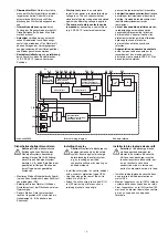
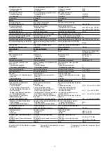
Technische Daten
Elektrische Daten
Versorgungsspannung U
B
Spannungstoleranz U
B
Leistungsaufnahme bei U
B
ohne Last
Restwelligkeit U
B
Ausgänge, Halbleiter:
Sicherheitsausgänge (S)
Hilfsausgang (S)
Schaltvermögen, Halbleiter
2 Ausgänge belastet
1 Ausgang belastet
Gesamtleistung ext. Last,
Halbleiter
Spannung und Strom an
Eingangskreis, Startkreis,
Rückführkreis
Hilfsausgang, Taktausgängen
UND/ODER-Eingängen
Geräteabsicherung
Max. Gesamtleitungswiderstand
R
lmax
(Eingangs-, Start- und
Rückführkreis)
Sicherheitstechnische Kenn-
daten
PL nach EN ISO 13849-1
Kaskadiereingang
HL-Ausgang
Kategorie nach EN 954-1
Kaskadiereingang
HL-Ausgang
SIL CL nach EN IEC 62061
Kaskadiereingang
HL-Ausgang
PFH nach EN IEC 62061
Kaskadiereingang
HL-Ausgang
24 V DC
80...125%
2 W
DC: 20%
2
1
U
B
≤
26,5 V: 2,0 A/50 W
U
B
> 26,5 V: 1,5 A/45 W
U
B
≤
26,5 V: 2,7 A/70 W
U
B
> 26,5 V: 2,2 A/65 W
130 W
24 V DC/ 5 mA
24 V DC/ 0,5 A
24 V DC/ 5 mA
max. 10 A flink/quick/rapide
oder/or/ou
max. 6 A träge/slow acting/
normal
2 kOhm
PL e (Cat. 4)
PL e (Cat. 4)
Cat. 4
Cat. 4
SIL CL 3
SIL CL 3
2,86E-10
3,44E-09
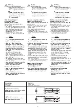
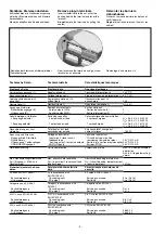
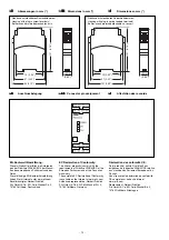
Steckbare Klemmen abziehen
Schraubendreher in Gehäuseaussparung
hinter der Klemme ansetzen und Klemme
heraushebeln.
Klemmen nicht an den Kabeln abziehen!
Abziehen der Klemmen am Beispiel einer
Schraubklemme
Remove plug-in terminals
Insert screwdriver into the cut-out of the
housing behind the terminal and lever the
terminal.
Do not remove the terminals by pulling the
cables!
How to remove the terminals using a screw
terminal as an example
Démonter les borniers
débrochables
Placer un tournevis derrière les bornes et
sortir le bornier.
Ne pas retirer les borniers en tirant sur les
câbles !
Démontage d’un bornier à vis
Technical details
Electrical data
Supply voltage U
B
Voltage tolerance U
B
Power consumption at U
B
without load
Residual ripple U
B
Semiconductor outputs
Safety outputs (N/O)
Auxiliary output(N/O)
Switching capability
2 outputs under load
1 output under load
Total power, ext. load,
semiconductor outputs
Voltage and current at
Input circuit, rreset circuit,
feedback loop
Auxiliary output, test pulse outputs
AND/OR inputs
Unit fuse protection
Max. overall cable resistance
R
lmax
(input circuit, reset circuit and
feedback loop)
Safety-related characteristic
data
PL in accordance with
EN ISO 13849-1
Cascading input
SC output
Category in accordance with
EN 954-1
Cascading input
SC output
SIL CL in accordance with
EN IEC 62061
Cascading input
SC output
PFH in accordance with
EN IEC 62061
Cascading input
SC output
Caractéristiques techniques
Données électriques
Tension d’alimentation U
B
Plage de la tension d'alimentation U
B
Consommation pour U
B
sans charge
Ondulation résiduelle U
B
Sorties statiques
Sorties de sécurité (F)
Sortie d'information (F)
Caractéristiques de commutation
2 sorties chargées
1 sortie chargée
Puissance total, charge ext.,
sorties statiques
Tension et courant sur
Circuit d’entrée, circuit de
réarmement, boucle de retour
Sortie d'info, sorties impulsionnelles
Entrées ET/OU
Protection du relais
Résistivité de câblage totale max.
R
lmax
(circuit d’entrée, de réarmement
et boucle de retour)
Caractéristiques techniques de
sécurité
PL selon EN ISO 13849-1
Entrée en cascade
Sortie HL
Catégorie selon EN 954-1
Entrée en cascade
Sortie HL
SIL CL selon EN IEC 62061
Entrée en cascade
Sortie HL
PFH selon EN IEC 62061
Entrée en cascade
Sortie HL
Содержание PNOZ e3.1p
Страница 11: ...11 Notizen Notes Notes...


