


- 4 -
Achtung!
UND-/ODER- Verknüpfung:
• Montieren Sie alle über die UND-/
ODER- Eingänge verknüpften
Geräte im gleichen Schaltschrank
oder
• Stellen Sie sicher, dass Fehler
über die Verbindung der Geräte
ausgeschlossen werden z.B. durch
geschützte Verlegung der
Verbindungsleitung.
Sicherheitsschaltgerät
in Betrieb nehmen
Inbetriebnahme vorbereiten
Beachten Sie bei der Vorbereitung der
Inbetriebnahme:
• Das Gerät und die Eingangskreise müssen
immer aus einem Netzteil versorgt werden.
• Verwenden Sie Leitungsmaterial aus
Kupferdraht mit einer Temperaturbe-
ständigkeit von 60/75°C.
• Berechnung der max. Leitungslänge I
max
am Eingangs-, Start- und Rückführkreis:
R
lmax
R
l
/ km
I
max
=
R
lmax
= max. Gesamtleitungswiderstand
(s. technische Daten)
R
l
/km = Leitungswiderstand/km
• Ausgang 14, 24: bei Leerlauf eine
Kapazität bis max. 2 nF ansteuerbar
• Setzen Sie die Sicherheitsausgänge 14
und 24 ausschließlich für sichere Anwen-
dungen ein. Die Sicherheitsausgänge
dürfen nicht mit SPS-Eingängen verbun-
den werden.
Um die Ausschaltimpulse an den
Halbleiterausgängen 14 und 24 zu
unterdrücken, setzen Sie die Reihen-
klemme mit Filter Bestellnummer 774195
oder 774196 ein.
• Der Ausgang Y32 ist ein Hilfsausgang
z. B. für die Kommunikation mit einer SPS
oder einer Anzeige.
• Verwenden Sie Freilaufdioden, wenn Sie
mit den Sicherheits-/Hilfsausgängen
Schütze oder Relais ansteuern.
Betriebsbereitschaft herstellen
• Legen Sie die Versorgungspannung an:
Klemme A1(+) : + 24 V DC
Klemme A2(-) : 0 V
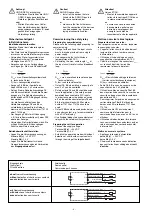
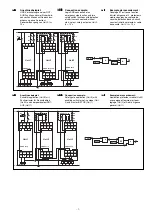
• Legen Sie die Betriebsart mit/ohne
Querschlusserkennung durch Verdrahten
des Eingangskreises fest.
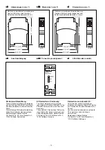
1
2
3
4
blau/blue/bleu
weiß/white/blanc
braun/brown/marron
schwarz/black/noir
S11
S12
S23
S24
Y4
S23
1
2
3
4
blau/blue/bleu
weiß/white/blanc
braun/brown/marron
schwarz/black/noir
A1
S12
S24
Y4
S11
Eingangskreis
Input circuit
Circuit d’entrée
Zweikanalig
Dual-channel
Commande par 2 canaux
ohne Querschlusserkennung
without detection of shorts across contacts
sans détection des court-circuits
mit Querschlusserkennung
with detection of shorts across contacts
avec détection des court-circuits
Caution!
AND-/OR connection:
•
Install all the devices that are
linked via the AND/OR inputs in
the same control cabinet
or
•
make sure that faults that occur
from the connection of the devices
can be excluded, e.g. by secure
laying of connection cables.
Commissioning the safety relay
Preparing for commissioning
Please note the following when preparing for
commissioning:
• Voltage for the unit and the input circuits
must always be provided from a single
power supply.
• Use copper wire that will withstand
temperatures of 60/75°C.
• Calculating the max. cable length I
max
at
the input circuit, reset circuit and feedback
loop:
R
lmax
R
l
/ km
I
max
=
R
lmax
= max. overall cable resistance (see
Technical details)
R
l
/km = cable resistance/km
• Output 14, 24: when idling, a capacity of a
max. 2 nF can be controlled
• Safety outputs 14 and 24 should be used
for safe applications. The safety outputs
must not be connected to PLC inputs.
In order to suppress the pulses on switch-
off on the semiconductor outputs 14 and
24, the terminal block with filter, order
number 774195 or 774196 should be
used.
• Output Y32 should be used exclusively as
an auxiliary output, e.g. for communication
with a PLC or display.
• Use flywheel diodes to drive contactors or
relays with the safety/auxiliary outputs.
Preparing the unit for operation
• Connect the supply voltage.
Terminal A1(+) : +24 VDC
Terminal A2(-) : 0 V
• Establish the operating mode with/without
detection of shorts across input contacts
through the wiring of the input circuit.
Attention!
Liaison ET/OU :
•
Montez l'ensemble des appareils
reliés via les entrées ET/OU dans
la même armoire électrique
ou
•
assurez-vous que la connexion
des appareils n'entraîne pas
d'erreurs, en protégeant, par
exemple, les câbles de
raccordement entre les appareils.
Mettre en service le bloc logique
Préparer la mise en service :
Pour préparer la mise en service, respectez
les consignes suivantes :
• L’appareil et les circuits d’entrée doivent
toujours être reliés à la même source
d'alimentation.
• Utilisez des fils de câblage en cuivre
supportant des températures 60/75°C.
• Calcul de la longueur de conducteur I
max
sur le circuit d’entrée, le circuit de
réarmement et boucle de retour :
R
lmax
R
l
/ km
I
max
=
R
lmax
= Résistivité de câblage totale max.
(voir les caractéristiques techniques)
R
l
/km = résistance du câble/km
• Sortie 14, 24 : en cas de coupure à vide,
capacité max. de 2 nF pilotable.
• Utilisez les sorties de sécurité 14 et 24
dans les circuits de sécurité. Les sorties de
sécurité ne doivent pas être raccordées à
des entrées d’API.
Pour supprimer l'impulsion de coupure aux
sorties statiques 14 et 24, utilisez les
bornes avec filtre, référence 774195 ou
774196.
• Utilisez la sortie Y32 exclusivement
comme sortie d'information pour la
communication par ex. avec un API ou un
afficheur.
• Utilisez des diodes de roue libre lorsque
vous commandez des contacteurs ou des
relais au moyen des sorties de sécurité/
d’information.
Mettre en œuvre le système
• Appliquez la tension d’alimentation.
borne A1(+) : + 24 V CC
borne A2(-) : 0 V
• Choisissez le mode avec/sans détection
des court-circuits par câblage du circuit
d’entrée.
Содержание PNOZ e3.1p
Страница 11: ...11 Notizen Notes Notes...


