


- 7 -
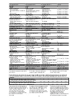
SIL nach IEC 61511
PFD nach IEC 61511
t
M
in Jahren
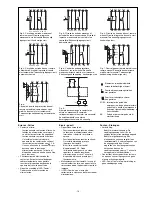
Zeiten
Einschaltverzögerung
automatischer Start
automatischer Start nach Netz-Ein
manueller Start
überwachter Start
Rückfallverzögerung
bei Not-Halt
bei Netzausfall
Wiederbereitschaftszeit bei max.
Schaltfrequenz 1/s
nach Not-Halt
nach Netzausfall
Min. Startimpulsdauer bei
überwachtem Start
Gleichzeitigkeit Kanal 1 und 2
Überbrückung bei
Spannungseinbrüchen
Umweltdaten
EMV
Schwingungen nach EN 60068-2-6
Frequenz
Amplitude
Klimabeanspruchung
Luft- und Kriechstrecken nach
EN 60947-1
Verschmutzungsgrad
Überspannungskategorie
Umgebungstemperatur
Lagertemperatur
Schutzart
Einbauraum (z. B. Schaltschrank)
Gehäuse
Klemmenbereich
Mechanische Daten
Gehäusematerial
Gehäuse
Front
Querschnitt des Außenleiters
(Schraubklemmen)
1 Leiter, flexibel
2 Leiter gleichen Querschnitts, flexi-
bel mit Aderendhülse, ohne
Kunststoffhülse
ohne Aderendhülse oder mit TWIN-
Aderendhülse
Anzugsdrehmoment für
Schraubklemmen
Abmessungen H x B x T
Einbaulage
Gewicht
SIL in accordance with IEC 61511
PFD in accordance with IEC 61511
t
M
in years
Times
Switch-on delay
automatic reset
automatic reset after power-ON
manual reset
monitored reset
Delay-on De-Energisation
at E-STOP
with power failure
Recovery time at max. switching
frequency 1/s
after E-STOP
after power failure
Min. start pulse duration with a
monitored reset
Simultaneity channel 1 and 2
Supply interruption before de-
energisation
Environmental data
EMC
Vibration to EN 60068-2-6
Frequency
Amplitude
Climate Suitability
Airgap Creepage in accordance with
EN 60947-1
Pollution degree
Overvoltage category
Ambient temperature
Storage temperature
Protection type
Mounting (eg. panel)
Housing
Terminals
Mechanical data
Housing material
Housing
Front panel
Cable cross section (screw
terminals)
1 core, flexible
2 core, same cross section flexible
with crimp connectors, without
insulating sleeve
without crimp connectors or with
TWIN crimp connectors
Torque setting for screw terminals
Dimensions H x W x D
Fitting Position
Weight
SIL selon IEC 61511
PFD selon IEC 61511
t
M
en années
Temporisations
Temps de réarmement
réarmement automatique
réarmement automatique après
mise sous tension
réarmement manuel
réarmement auto-contrôlé
Temps de retombée
en cas d'arrêt d'urgence
en cas de coupure d'alimentation
Temps de remise en service en cas de
fréquence de commutation max. 1/s
arrêt d'urgence
après une coupure d'alimentation
Durée minimale de l'impulsion pour
un réarmement auto-contrôlé
Désynchronisme canal 1 et 2
Tenue aux micro-coupures
Données sur l'environnement
CEM
Vibrations selon EN 60068-2-6
Frequence
Amplitude
Conditions climatiques
Cheminement et claquage selon
EN 60947-1
Niveau d'encrassement
Catégorie de surtensions
Température d’utilisation
Température de stockage
Indice de protection
Lieu d'implantation (ex. armoire)
Boîtier
Bornes
Données mécaniques
Matériau du boîtier
Boîtier
Face avant
Capacité de raccordement
(borniers à vis)
1 conducteur souple
2 conducteurs de même diamètre
souple avec embout, sans chapeau
plastique
souple sans embout ou avec
embout TWIN
Couple de serrage (borniers à vis)
Dimensions H x P x L
Position de travail
Poids
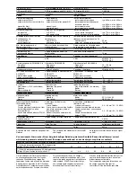
SIL 3
2,03E-06
20
typ. 330 ms, max. 450 ms
typ. 330 ms, max. 480 ms
typ. 335 ms, max. 450 ms
typ. 330 ms, max. 450 ms
typ. 17 ms, max. 30 ms
typ. 40 ms, max. 60 ms
50 ms
100 ms
30 ms
∞
10 ms
EN 60947-5-1,
EN 61000-6-2
10 ... 55 Hz
0,35 mm
EN 60068-2-78
2
III
-10 ... + 55 °C
-40 ... +85 °C
IP54
IP40
IP20
PPO UL 94 V0
ABS UL 94 V0
0,2 ... 4,0 mm
2
, 24 ... 10 AWG
0,2 ... 2,5 mm
2
, 24 ... 14 AWG
0,2 ... 2,5 mm
2
, 24 ... 14 AWG
0,6 Nm
87 x 90 x 121
mm
beliebig/any/indifférente
640 g
Es gelten die 09/01 aktuellen Ausgaben der
Normen
The version of the standards current at 09/01
shall apply
Se référer à la version des normes en vigeur
au 09/01.
Um ein Versagen der Geräte zu verhindern,
an allen Ausgangskontakten für eine aus-
reichende Funkenlöschung sorgen. Bei
kapazitiven Lasten sind eventuell auftretende
Stromspitzen zu beachten. Bei DC-Schützen
Freilaufdioden zur Funkenlöschung einsetzen,
um die Lebendauer der Schütze zu erhöhen.
To prevent failure of the unit, all output
contacts should be fused adequately. With
capacative loads, possible current peaks are
to be avoided. With DC contactors/relays
use suitable spark suppression to ensure
extended life of the contactors/relays.
Prévoir un dispositif d’extinction d’arc sur les
contacts de sortie pour éviter un éventuel
disfonctionnement du relais.
Tenir compte des pointes d’intensité en cas
de charge capacitive. Equiper les
contacteurs DC de diodes de roue libre .
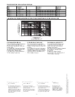
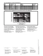
Anzahl der Kontakte/number of contacts/nombre des contacts
7
6
5
4
3
2
1
I
th
(A) bei Versorgungsspannung DC/with operating
voltage DC/pour tension d’alimentation CC
5,2
5,6
6,2
6,9
8,0
8,0
8,0
I
th
(A) bei Versorgungsspannung AC/with operating
voltage AC/pour tension d’alimentation AC
4,5
4,8
5,3
5,9
6,8
8,0
8,0
Konventioneller thermischer Strom bei gleichzeitiger Belastung mehrerer Kontakte/Conventional thermal current
while loading several contacts/Courant thermique conventionnel en cas de charge sur plusieurs contacts


