OPERATING AND INSTALLATION INSTRUCTIONS LG 250 A
PAGE 12
Changes reserved
U
S
ER
G
ENER
A
L
S
P
EC
IA
LIS
T
P
ER
S
O
NNEL
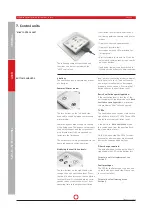
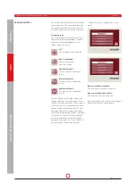
4 buttons
The ventilation unit is operated by means
of 4 buttons.
Summer/Winter mode:
The two buttons on the left-hand side
are used to switch between summer and
winter mode.
Summer/bypass modes support cooling
of the living area. The bypass circumvents
the heat exchanger and the cold outdoor
air is blown directly or via a ground col-
lector into the living area.
The outdoor air is always conveyed via the
heat exchanger in winter operation.
Modifying the ventilation levels:
The two buttons on the right-hand side
change the unit’s ventilation level. Press-
ing the [+] button increases the ventilation
level until level III is reached which corre-
sponds to boost ventilation. After 1 hour
operating time in the highest ventilation
level, normal ventilation mode is automat-
ically reset to Level 2. The boost ventila-
tion may, alternatively, also be stopped
manually after one hour. Pressing the [-]
button reduces the ventilation level.
Basic Ventilation operating mode:
If the ventilation level is less than I, the
unit switches to Standby mode or to
Basic
Ventilation operating mode.
A minimum
volume flow of 30 m³/h is configured.
7 LEDs:
The ventilation unit's various statuses are
signalled via a total of 7 LEDs. Three LEDs
display the current ventilation level.
If the unit is in
"Basic Ventilation"
mode,
this can be seen from the gentling flash-
ing of ventilation level I.
On the left-hand side, the LEDs for sum-
mer and/or winter modes are arranged
beside the corresponding buttons.
Filter change required:
The potential need to change the filter is
signalled by the LED on the bottom left.
For details on filter replacement, see
Section 9.
Fault messages
The LED for fault messages can be seen
on the lower right-hand side. Please con-
tact your installer!
For details on fault messages, see
Section 8.
BUTTONS AND LEDS
The following compact ventilation unit
functions can be configured with the
"MINI" control unit.
• Ventilation level of the ventilation unit.
•
Switching between summer and winter
modes.
• Display of filter change messages.
•
Display of possible fault
messages with the LEDs provided for
this purpose.
•
Air flow volume for levels I to III can be
adjusted in certain areas using a combi-
nation of buttons.
•
In addition, the unit can be switched to
Standby mode or Basic Ventilation mode.
"MINI" CONTROL UNIT
7. Control units


