Phytec nanoModul-164 Скачать руководство пользователя страница 58

nanoMODUL-164 QuickStart Instructions


54

 PHYTEC Meßtechnik GmbH 2003     L-379e_4

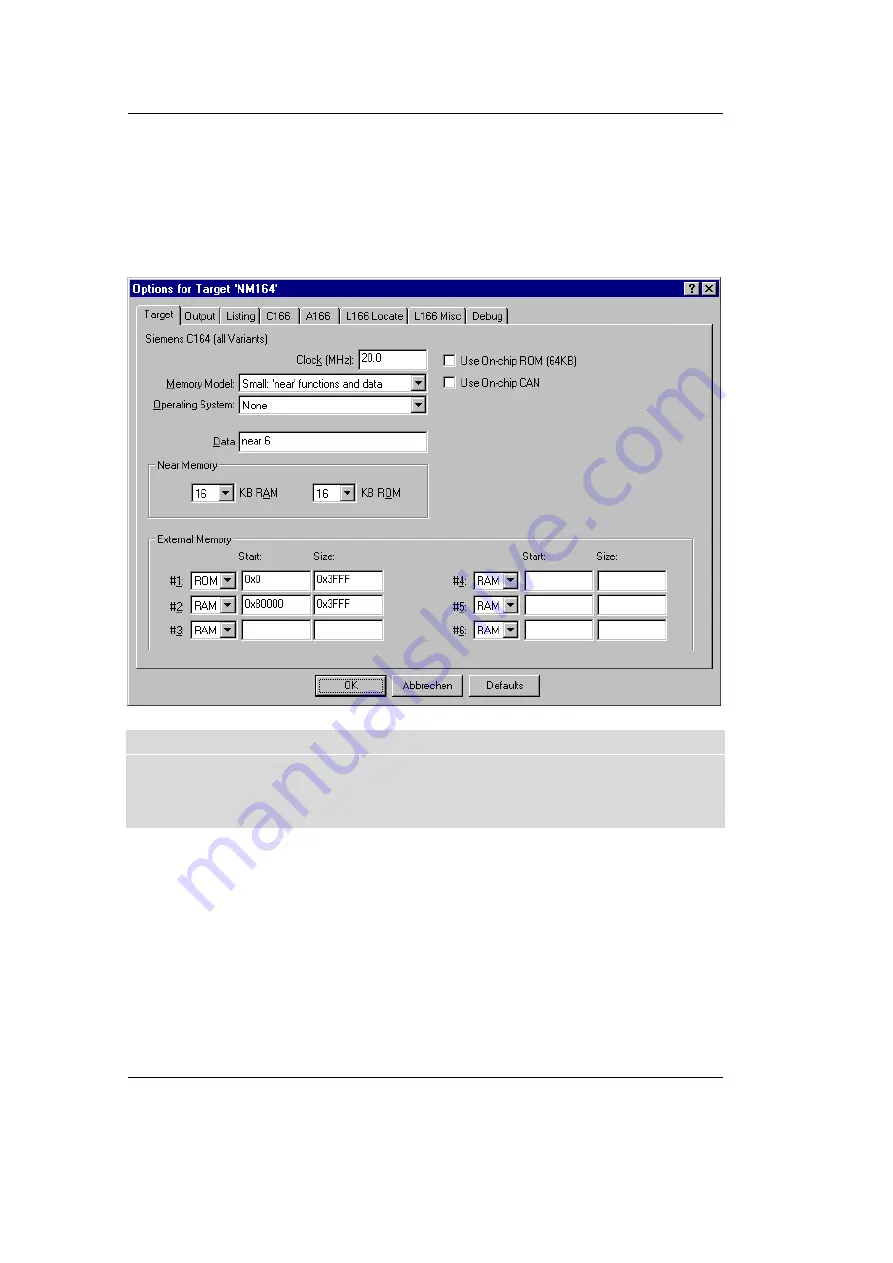
To configure the Target:


Open the Project|Options for Target ‘NM164’ menu and type
the settings for the External Memory as shown below.
Make sure that #1 is set to ROM.

If you have a nanoModul-164 with 1 MB SRAM or 1 MB use the
following settings for the External Memory:
#1

0x0           - 0x3FFF

#2

0x100000 - 0x3FFF

Содержание nanoModul-164

Страница 1: ...ODUL 164 QuickStart Instructions Using PHYTEC FlashTools for Windows and the Keil µVision2 Software Evaluation Development Tool Chain Note The PHYTEC Spectrum CD includes the electronic version of the English nanoMODUL 164 Hardware Manual Edition May 2003 ...

Страница 2: ...tionally PHYTEC Meßtechnik GmbH offers no guarantee nor accepts any liability for damages arising from the improper usage or improper installation of the hardware or software PHYTEC Meßtechnik GmbH further reserves the right to alter the layout and or design of the hardware without prior notification and accepts no liability for doing so Copyright 2003 PHYTEC Meßtechnik GmbH D 55129 Mainz Rights i...

Страница 3: ...ing Example Code with FlashTools for Windows 32 2 3 3 1 Hello 37 2 3 3 2 Blinky 42 3 Getting More Involved 45 3 1 Starting the µVision2 Tool Chain 45 3 2 Creating a New Project and Adding an Existing Source File 46 3 3 Modifying the Source Code 52 3 4 Saving the Modifications 53 3 5 Setting Options for Target 53 3 6 Building the Project 56 3 7 Downloading the Output File 57 3 7 1 Downloading with ...

Страница 4: ... Single Stepping 76 4 6 1 Memory Window 77 4 6 2 Watch Window 78 4 7 Resetting Simulator and the nanoMODUL 164 79 5 Advanced User Information 81 5 1 FlashTools 81 5 1 1 FlashTools for DOS 81 5 1 2 FlashTools for Windows 82 5 2 Start164 a66 83 5 3 Linking and Locating 84 5 4 Debugging using Monitor kernel 86 Appendices 89 A Troubleshooting 89 A I µVision2 debugger in Monitor mode 89 A II Monitor Co...

Страница 5: ...ures as Jumper configuration memory mapping and pin layout Selecting the links on the electronic version of this document links to the applicable section of the nanoMODUL 164 Hardware Manual 1 1 Documentation Overview This Rapid Development Kit includes the following electronic documentation on the enclosed PHYTEC Spectrum CD ROM the PHYTEC nanoMODUL 164 Hardware Manual and Development Board Hardw...

Страница 6: ...MODUL 164 using the Windows based µVision2 tool 3 The Debugging section provides a third example program Debug to demonstrate monitoring of the board and simple debug functions using the µVision2 debug environment In addition to dedicated data for this Rapid Development Kit this CD ROM contains supplemental information on embedded microcontroller design and development 1 3 System Requirements Use ...

Страница 7: ...standard module runs at a 20 MHz internal clock speed delivering 100 instruction cycles ns and offers 256 kByte up to 1 MB SRAM and 256 kByte up to 1 MB Flash on board for DATA and CODE storage PHYTEC FlashTools for Windows enable easy on board download of user code to the external Flash device The nanoMODUL 164 is fitted with one RS 232 transceiver an I C RTC and a CAN bus interface All controlle...

Страница 8: ...face battery buffered Real Time Clock and SRAM prepared for operation with in circuit emulators such as ICE connect 16x requires only 5V 300 mA power source in a temperature range of 0 to 70 degree C The PHYTEC Development Board in EURO card dimensions 160 x 100 mm is completely equipped with all mechanical and electrical components necessary for the speedy and secure insertion and subsequent prog...

Страница 9: ... low voltage socket and voltage regulator accepting an unregulated input voltage in a range from 8 to 12 VDC DB 9 connector configured as an RS 232 interface second DB 9 interface for CAN VG96 connector simple jumper configuration wire wrap field 64 x 69 mm supporting development of user designed peripheral hardware ...

Страница 10: ...ile into an Intel hexfile that is suitable for programming into an EPROM device or downloading into the Flash on the PHYTEC nanoMODUL 164 target board µVision2 consists of the following executables C Compiler c166 exe Assembler a166 exe Linker l166 exe Converter oh166 exe µVision2 uv2 exe a Windows based application Once installed the default destination location for these files is the C C166eval ...

Страница 11: ...C164CI 165 166 167 167CR and future derivatives The C166 compiler easily integrates into the Keil RTOS and interfaces and passes debug information to the µVision2 simulator and all in circuit emulators Extensions provide access to on chip peripherals The Keil C166 compiler provides the fastest and smallest code using industry benchmarks A166 and A51 Macroassemblers These two macroassemblers includ...

Страница 12: ...ts on the PHYTEC target board The full version has no restrictions and is completely ANSI compliant FR166 Full Function RTOS for the Infineon C166 Family The FR166 is a multitasking real time operating system for the Infineon 166 family Multiple tasks can be managed by you on a single CPU making your programs much easier to develop The RTX166 Full includes CAN libraries The RTX166 Tiny is a subset...

Страница 13: ...loading example user code in hexfile format from a host PC to the external Flash Memory using FlashTools 2 1 Installing Rapid Development Kit Software When inserting the PHYTEC Spectrum CD into the CD ROM drive of your host PC the PHYTEC Spectrum CD should automatically launch a setup program that installs the software required for the Rapid Development Kit as specified by the user Otherwise the s...

Страница 14: ...tallation of Rapid Development Kit software and documentation The default destination location is C PHYBasic All path and file statements within this QuickStart Instruction are based on the assumption that you accept the default install paths and drives If you decide to individually choose different paths and or drives you must consider this for all further file and path statements We recommend th...

Страница 15: ...st of available products By using the Change button advanced users can select in detail which options should be installed for a specific product All Kit specific content will be installed to a Kit specific subdirectory of the Rapid Development Kit root directory that you have specified at the beginning of the installation process ...

Страница 16: ...he documentation to your hard drive you will need the PHYTEC Spectrum CD ROM each time you want to access these documents The installed links will refer to your CD ROM drive in this case If you decide to copy the electronic documentation to your hard drive the documentation for this nanoMODUL 164 Kit will also be installed to the Kit specific subdirectory The manuals of the Development Boards are ...

Страница 17: ...l Chain After accepting the Welcome window and license agreement select the destination location for installation ofthe Development Tool Chain Depending on the Rapid Development Kit software you have selected the applicable Keil µVision2 Evaluation Development tool chain will be installed to your hard drive Additional software such as Adobe Acrobat Reader will also be offered for installation ...

Страница 18: ...functional problems We recommend that you install µVision2 from the Spectrum CD ROM even if other versions of µVision2 are already installed on your system These QuickStart Instructions and the demo software included on the CD ROM have been specifically tailored for use with one another In the following windows you can decide to install FlashTools for Windows Beta Version and the Acrobat Reader Fo...

Страница 19: ...Getting Started PHYTEC Meßtechnik GmbH 2003 L 379e_4 15 Press Finish to complete the installation and decide if you want to begin the Quickstart Instruction immediately ...

Страница 20: ...footprint X3 as shown in the Figure below Ensure that there is a solid connection between the modul pins and the Development Board receptacle Also take precautions not to bend the pins when the nanoMODUL is removed from and inserted onto the Development Board Figure 1 Development Board Overview Configure the Jumpers on the Development Board as indicated below This correctly routes the RS 232 signa...

Страница 21: ... P3 to a power supply refer to Figure 3 for the right polarity 8 12VDC GND 500mA center hole 2 0mm 5 5mm polatity Figure 3 Power Connector Simultaneously press the Reset S1 and Boot S2 switches on the Development Board first releasing the Reset S1 and then two or three seconds later release the Boot S2 switch This sequence of pressing and releasing the Reset S1 and Boot S2 switches renders the nan...

Страница 22: ...um CD FlashTools consists of three files the flasht exe user interface as DOS executable file boot the second stage loader and flash the FlashTools microcontroller firmware FlashTools for DOS flasht exe is a utility program that allows download of user code in h86 file format from a host PC to a PHYTEC Single Board Computer SBC via an RS 232 connection FlashTools uses the Bootstrap Loader mechanis...

Страница 23: ...r to section 5 1 1 for details You can start FlashTools for DOS for your nanoMODUL 164 by selecting either the FlashTools COM1 or FlashTools COM2 icon within the Programs PHYTEC Rapid Development Kit nanoMODUL 164 program group We always recommend to use the installed icons If you have a nanoModul 164 with 1 MB SRAM or 1 MB Flash use the icons FlashTools Max COM1 or FlashTools Max COM2 You can als...

Страница 24: ...ax COM2 The microcontroller firmware tries to automatically adjust to the baud rate entered in the command line within the properties of the link However it may occur that the predefined baud rate can not be reached This results in FlashTools omitting the loading procedure and never showing the main menu In this case try incrementally lower baud rates to establish a connection Before further conne...

Страница 25: ...hnik GmbH 2003 L 379e_4 21 After FlashTools has loaded the main menu appears on the screen At the FlashTools main menu you will see commands for the following Flash Status information shows sector and address ranges in Flash memory ...

Страница 26: ...EC Meßtechnik GmbH 2003 L 379e_4 Erase entire Flash area enables erasure of the unprotected sectors of the whole user addressable Flash Erase partial Flash area enables erasure of user specified sectors of memory by entering a memory address range ...

Страница 27: ...TEC Meßtechnik GmbH 2003 L 379e_4 23 Load INTEL hexfile downloads specified hexfiles to the target hardware Software Reset forces a software reset of the microcontroller resulting in execution of the Flash memory content ...

Страница 28: ...ion at a user specified address Erase Load and Software Reset results in automatic erasure of unprotected areas of the Flash loading of a hexfile and a subsequent software reset that executes the contents of the Flash memory Return to the main FlashTools menu to run an example program as described in the next section ...

Страница 29: ...sectors are erased the main menu reappears Enter 4 to choose the Load INTEL hexfile command and press function key F2 to specify the input file for download The hexfile has already been installed on your hard disk during the installation procedure Enter the correct drive and path to the nanoMODUL 164 Demo file default location C PHYBasic nM164 Demos Keil Hello hello h86 After pressing the Return k...

Страница 30: ...re xxxx is the erroneous address If this occurs press the Space bar to return to the main menu this may take some time and select the 2 Erase entire Flash Area from the main menu to erase all unprotected sectors of the Flash Then repeat the download procedure From within the main menu press function key F1 Select Y to exit the FlashTools Monitoring the execution of the QuickStart demo requires use...

Страница 31: ...ow will now appear Enter COM1 Direct in the Name combobox be sure to specify the correct COM parameter for your system Next press the Ok button This creates a new HyperTerminal session named COM1 Direct and advances you to the next HyperTerminal window The New Connections Properties window will now appear Specify Direct to COM1 under the Connect Using combobox be sure to indicate the correct COM s...

Страница 32: ...Properties window to advance to the next window COM1 Properties Then set the following COM parameters Bits per second 9600 Data bits 8 Parity None Stop Bits 1 Flow Control None Selecting OK advances you to the COM1 Direct HyperTerminal monitoring window Notice the connection status report in the bottom lower corner of the window ...

Страница 33: ...ute the hello h86 file loaded into the Flash Successful execution will send the character string Hello World from the target hardware to the HyperTerminal window Click the disconnect icon If no output appears in the HyperTerminal window check the power supply the COM parameters and the RS 232 connection ...

Страница 34: ... directory 2 3 2 2 Blinky The Blinky example sends a program to the Flash that when executed manipulates the single user SMD LED D1 on the Development Board that is mounted near the Boot S2 switch This second example program provides a review of the FlashTools download procedure Ensure that the target hardware is properly connected to the host PC and a power supply Reset the target hardware and fo...

Страница 35: ...PHYBasic nM164 Demos Keil Blinky blinky h86 If you have a nanoModul 164 with 1 MB SRAM or 1 MB Flash use the Demo file at the default location C PHYBasic nM164 Demos Keil Blinky BlinkyMx BlinkyMx h86 Returning to the main menu enter 5 to choose the Software Reset command This will render a software reset to the target system and start execution of the download program Successful execution of the p...

Страница 36: ...ls for Windows by double clicking on the FlashTools for Windows icon or by selecting FlashTools for Windows from within the Programs PHYTEC FlashTools for Windows program group The Connect tab of the FlashTools for Windows Worksheet window will now appear Double click on 16 Bit RS232 Select the correct module from the list and press the Connect button ...

Страница 37: ... hardware The microcontroller tries to automatically adjust to the baud rate selected within the baud rate tab However it may occur that the selected baud rate can not be reached This results in a connection error In this case try other baud rates to establish a connection Before further connection attempts be sure to reset the target hardware and render it into Bootstrap mode as described in sect...

Страница 38: ...hnik GmbH 2003 L 379e_4 After the data transfer you will see FlashTools for Windows Worksheet window with the following tabs Flash Information shows sector and address ranges in Flash Memory File Download downloads specified hexfiles to the target hardware ...

Страница 39: ...Getting Started PHYTEC Meßtechnik GmbH 2003 L 379e_4 35 Protected Areas Information shows protected areas of Flash Memory Sector Utilities allow erasure of individual sectors of Flash Memory ...

Страница 40: ...t Instructions 36 PHYTEC Meßtechnik GmbH 2003 L 379e_4 Communication Setup provides you with the possibility to disconnect the target and reconnect with an equal one Programming of several targets is possible for you thereby ...

Страница 41: ...the Flash sector s being erased at the bottom left hand of the window When the desired sectors are erased the connection properties description returns to the lower left corner of the window Choose the File Download tab and click on the File Open button The hexfile has already been installed to your hard drive during the installation procedure Type in the correct drive and path to the nanoMODUL 16...

Страница 42: ...alog box will appear indicating Location not empty Please erase location and try again In this event select the Sector Erase tab from the FlashTools for Windows worksheet highlight Sector 0 and erase the sector Then repeat the download procedure Returning to the Communication Setup tab click on the Disconnect button and exit the Flashtools Monitoring the execution of the QuickStart demo requires u...

Страница 43: ...o specify the correct COM parameter for your system Next press the Ok button This creates a new HyperTerminal session named COM1 Direct and advances you to the next HyperTerminal window The New Connections Properties window will now appear Specify Direct to COM1 under the Connect Using combobox be sure to indicate the correct COM setting for your system ...

Страница 44: ...Properties window to advance to the next window COM1 Properties Then set the following COM parameters Bits per second 9600 Data bits 8 Parity None Stop Bits 1 Flow Control None Selecting OK advances you to the COM1 Direct HyperTerminal monitoring window Notice the connection status report in the bottom lower corner of the window ...

Страница 45: ...rt of your nanoMODUL 164 to 9600 baud The initialization values are based on the assumption that the microcontroller runs at a 20 MHz internal clock frequency Please note that the nanoMODUL 164 is populated with an oscillator with a frequency of just 5 MHz An internal PLL Phase Locked Loop device renders an internal 20 MHz clock frequency If your nanoMODUL 164 is equipped with an oscillator with a...

Страница 46: ...shTools for Windows Worksheet specify the proper serial port and transmission speed for communication between host PC and target hardware and click the Load Flashtools button to transfer the modul based part of the FlashTools for Windows to the target hardware Select the right protocol default RS232 for further use of the FlashTools for Windows Returning to the FlashTools for Windows Worksheet cho...

Страница 47: ... Communication tab click on the Disconnect button Press the Reset button S1 on the Development Board to reset the target hardware and to start execution of the downloaded software Successful execution of the program will flash the LED with equal on and off durations You have now successfully downloaded and executed two pre existing example programs in h86 file format ...

Страница 48: ...nanoMODUL 164 QuickStart Instructions 44 PHYTEC Meßtechnik GmbH 2003 L 379e_4 ...

Страница 49: ...l Chain The µVision2 evaluation software development tool chain should have been installed during the install procedure as described in section 2 1 You can also manually install µVision2 by executing setup exe from within the Software Keil Ek166 directory of your PHYTEC Spectrum CD Start the tool chain by selecting µVision2 from within the Programs program group After you start µVision2 the window...

Страница 50: ...New Project and Adding an Existing Source File Open the Project menu and choose New Project This opens a standard Windows dialog that asks you for the new project file name Change to the project directory created by the installation procedure default location C PHYBasic nM164 Demos Keil Blinky2 ...

Страница 51: ...he name Blinky2 and press Save Now use from the menu Project Select Device for Target and double click on Siemens as manufacturer for the CPU The nanoMODUL 164 is equipped with a C164 CPU Choose this controller type from the list as shown below This selection sets necessary tool options for the C164 device and simplifies in this way the tool configuration Press the OK button ...

Страница 52: ...e default Target 1 in the project window and click on it Change the name into NM164 and press return Select the file group Source Group 1 in the Project Window Files page and click on it to change the name into User Click with the right mouse key in the Project Window to open a local menu Choose the options Targets Groups Files ...

Страница 53: ... PHYTEC Meßtechnik GmbH 2003 L 379e_4 49 Select the tab Groups Add Files and type the new group name System Files in the Group to Add section Click on Add and then on OK Your project file structure should now look like this ...

Страница 54: ...o add some source code to our project To do so click with the right mouse key on the User group to open a local menu The option Add Files to Group User opens the standard files dialog Select the file Blinky2 c Choosing Add adds the Blinky2 c file to your current project window Close the window ...

Страница 55: ... ASM source file a see this file Your project window should now look like this At this point you have created a project called blinky2 uv2 and added an existing C source file called blinky2 c and an existing assembler file called start164 a66 Next you modify the C source before building your project This includes compiling linking locating and creating the hexfile ...

Страница 56: ...de section Modify the section shown below the values shown in bold and italic from the original 150 000 counts to the indicated values while 1 loop forever P8_0 0 output to LED port for i 0 i 225000 i delay for 150000 counts wait call wait function P8_0 1 output to LED port for i 0 i 75000 i delay for 150000 counts wait call wait function This will change the on off ratio of the blinky program ...

Страница 57: ...rol compiling and linking source files in several programming languages Before using the Make utility macroassembler C compiler or linker you must configure the corresponding options Most of the options are set by specifying the device for the project Only the external memory and output options must be set Enter the changes as indicated below and leave all other options set to their default values...

Страница 58: ...gure the Target Open the Project Options for Target NM164 menu and type the settings for the External Memory as shown below Make sure that 1 is set to ROM If you have a nanoModul 164 with 1 MB SRAM or 1 MB use the following settings for the External Memory 1 0x0 0x3FFF 2 0x100000 0x3FFF ...

Страница 59: ...nvolved PHYTEC Meßtechnik GmbH 2003 L 379e_4 55 To configure the Output options Select the Output tab and activate the Create HEX File option With this option a INTEL HEX file will be created for download Click on OK ...

Страница 60: ...they will be shown in an error dialog box on the screen If there are no errors the code is assembled and linked and the ex ecutable code is ready to be downloaded to the board This is shown in the Output Window which indicates Blinky2 0 Errors 0 Warnings The code to be downloaded to the board will be the name of the project with h86 as file name extension in this case blinky2 h86 If a list of erro...

Страница 61: ... S1 and then the Boot S2 switch Start FlashTools for DOS for your nanoMODUL 164 by selecting either the FlashTools COM1 or FlashTools COM2 icon within the PHYTEC Rapid Development Kit nanoMODUL 164 program group Which icon to choose depends on the serial port used to connect to the target system If you have a nanoModul 164 with 1 MB SRAM or 1 MB Flash use the icon s FlashTools Max COM1 or FlashToo...

Страница 62: ...ectors are erased the main menu reappears Enter 4 to choose the Load INTEL hexfile command and press function key F2 to specify the input file The hexfile for download was created during the Make process and is located in the directory of the Blinky2 project Enter the correct drive and path to the Blinky2 hexfile default location C PHYBasic nM164 Demos Keil Blinky2 blinky2 h86 The download immedia...

Страница 63: ...a from the main menu to erase all unprotected sectors of the Flash memory Then repeat the download procedure After the download is finished FlashTools will return to the main menu automatically Press function key F1 and select Y to confirm that you wish to exit FlashTools Press the Reset button S1 on the Development Board If the modified hexfile properly downloads and executes the LED should now f...

Страница 64: ...right protocol default RS232 for further use of the FlashTools for Windows Returning to the FlashTools for Windows Worksheet choose the Sectors Utilities tab highlight Sector 0 in the Sectors Erase section of the tab and click on the Erase Sector s button to erase this memory sector Wait until the status check in the lower left corner of the FlashTools for Windows Worksheet finishes returning the ...

Страница 65: ...the host PC to the target hardware For detailed commentary on each step described below in concise form refer back to the Blinky example starting at section 3 2 3 8 1 Creating a New Project Start the Keil µVision2 environment and close all projects that might be open Open the Project menu and create a new project called hello2 uv2 within the existing project directory C PHYBasic nM164 Demos Keil H...

Страница 66: ...window 3 8 3 Setting Options for Target Modify the default options for the Target by defining the following external memory spaces ROM Start 0x0 Size 0x3FFF RAM Start 0x80000 Size 0x3FFF If you have a nanoModul 164 with 1 MB SRAM or 1 MB use the following external memory spaces ROM 0x0 0x3FFF RAM 0x100000 0x3FFF Modify the default options for the output file by selecting the Create HEX File checkb...

Страница 67: ...source file of the project contains any errors they will be shown in an error dialog box on the screen Use the editor to correct the error s in the source code and save the file and repeat this section If there are no errors the code is assembled and linked and the executable code is ready to be downloaded to the board ...

Страница 68: ...1 MB SRAM or 1 MB Flash use the icon s FlashTools Max COM1 or FlashTools Max COM2 FlashTools will load to the RAM of the nanoMODUL 164 The active loading process is indicated by a rotating cursor bar After FlashTools has loaded the main FlashTools menu appears on the screen Enter 2 to choose the Erase entire Flash Area command and enter Y to confirm erasure of all unprotected sectors of Flash memo...

Страница 69: ...s not empty i e erased a warning dialog box will appear indicating Target address location not empty xxxx where xxxx is the erroneous address In this case press the Space bar to return to the main menu this may take some time and select the 2 Erase entire Flash Area from the main menu to erase all unprotected sectors of the Flash memory Then repeat the download procedure After the download is fini...

Страница 70: ...e target hardware Select the right protocol default RS232 for further use of the FlashTools for Windows Returning to the FlashTools for Windows Worksheet choose the Sectors Utilities tab highlight Sector 0 in the Sectors Erase section of the tab and click on the Erase Sector s button to erase this memory sector Wait until the status check in the lower left corner of the FlashTools for Windows Work...

Страница 71: ... Parity None Stop Bits 1 Flow Control None Resetting the Development Board at S1 will execute the hello2 h86 file loaded into the Flash Successful execution will send the modified character string PHYTEC Stick it in to the HyperTerminal window Click the Disconnection icon Close the HyperTerminal program You have now modified source code recompiled the code created a modified download hexfile and s...

Страница 72: ...nanoMODUL 164 QuickStart Instructions 68 PHYTEC Meßtechnik GmbH 2003 L 379e_4 ...

Страница 73: ...t that simulates most features of the 166 ST10 microcontroller family without actually having target hardware You can test and debug your embedded application before the hardware is ready µVision2 simulates a wide variety of peripherals including the serial port external I O and timers The peripheral set is selected when you select a CPU from the device database for your target Use Advance GDI dri...

Страница 74: ...mbH 2003 L 379e_4 4 1 Loading the Example File Within the default location C PHYBasic mM164 Demos Keil Debug you will find an already build project called Debug Close all possible open projects and open the project Debug uv2 with the option Project open Project ...

Страница 75: ...sing the Bootstrap mode Depending on the Project Options for Target nM164 Debug configuration µVision2 will load the application program and run the startup code Please select the check boxes near Use Keil Monitor 166 Driver and Load Aplication at Startup in the Project Options for Target nM164 Debug dialog Click on the Settings button in the upper right corner of the Options for Target nM164 wind...

Страница 76: ...r Configuration listbox A short description for the selected module is shown in the Description section on the right side If you have a nanoModul 164 with 1 MB SRAM or 1 MB select Phytec nM164 1MB from the Monitor Configuration listbox Select the right COM Port in the PC Port Settings Click on OK Click on OK again ...

Страница 77: ...oot S2 switch Since the required microcontroller portion to communicate with the Keil Monitor 166 will be automatically downloaded using the Bootstrap mode there is no further preparation of the target system 4 4 Starting the Debugger To start the µVision2 debug environment click on the debugger icon on the µVision2 toolbar You will see a blue bar growing from left to right at the button of your s...

Страница 78: ...u will see the source code on your screen in the Disassembly Window Note that you will not see your C source code because the program starts at 00000H which is the reset vector with some assembler instructions There is an assembler jump to a section of initialization code which then branches to your C main program In this example you will see the JMPS instruction at 0000H and some parts of the C c...

Страница 79: ...ng the Keil µVision2 Debug Features 4 5 1 Breakpoints Click on a memory location such as line number 42 first x A colored bar appears marking this position You can click on Run to Curser line to reach this point or you can double click and set a breakpoint Set a breakpoint here with the double click The red mark on the left hand of the selected line indicates the breakpoint Click on RUN and the pr...

Страница 80: ...with 3 at each run Remove the breakpoint at line 48 with a double mouse click 4 6 Single Stepping The debugger uses Step Into to single step one instruction at a time Step Into is also used to enter a function in the same fashion Step Over means to skip over a function that you are not interested in Step Out is used to exit a function you are currently in Step Out is very useful if you find yourse...

Страница 81: ...g the next return instruction As you step through the program the appropriate values in the Regs window will change colour as their values are updated Most of the variables have been allocated to fast internal CPU registers by the µVision2 compiler 4 6 1 Memory Window If the Memory Window is not already visible activate it by selecting View Memory window from the µVision2 tool bar Type 0x5000 at t...

Страница 82: ...n the Project window and double click on the Debug c filename to open it Scroll down till you could see the yellow program counter arrow Click on the Watch 1 tab at the bottom of the Watch Window To add variable symbols just click with the right mouse button on the symbol name in you source code and choose Add to Watch Window Add the variables bigcount and first to WatchWindow 1 Till first is a st...

Страница 83: ...cation was started It is not as complete as a hardware reset pressing S1 on the Development Board The best method of stopping a running application is to press the Halt button rather than the Reset CPU in Monitor mode Halt tries to stop a running application when the Serial interrupt or NMI option is enabled If this option is not enabled a dialog box is displayed in which you can select the next s...

Страница 84: ...nanoMODUL 164 QuickStart Instructions 80 PHYTEC Meßtechnik GmbH 2003 L 379e_4 ...

Страница 85: ...the Flash Additionally the re programmable Flash device on the nanoMODUL 164 enables easy update of user code and the target application in which the nanoMODULl 164 has been implemented Currently the nanoMODUL 164 can be populat with three different sized Flash devices a 29F200 with 256 KB a 29F400 with 512 KB or a 29F800 with 1 MB FlashTools always uses the Bootstrap mode to transfer the required...

Страница 86: ...e to transfer executable code to the nanoMODUL 164 that in turn download user code into the Flash Additionally the re programmable Flash device on the nanoMODUL 164 enables easy update of user code and the target application in which the nanoMODUL 164 has been implemented Currently the nanoMODUL 164 can be populat with three different sized Flash devices a 29F200 with 256 kByte a 29F400 with 512 k...

Страница 87: ...l execute prior to the execution of user code To ensure this it is recommended that the startup code occupy the Reset vector of the application which is the location the microcontroller starts execution after Reset 0x0000 After performing the initialisation steps your individual main function is called by the start up code To accommodate the start up code to the needs of your application copy it f...

Страница 88: ... code during runtime It is usually very difficult to detect such a mistake We recommend to always move start164 a66 to the end of your projects file list 5 3 Linking and Locating The Linker has to combine several re locatable object modules contained in object files and or libraries to generate a single absolute object In addition the Linker must locate several segments of type code constants and ...

Страница 89: ... all xCODE and xCONST classes must be located to any internal non volatile memory e g Flash OTPROM of the C164 or any external Flash Memory of the nanoMODUL 164 A near address data area NDATA NDATA0 must reside in one data page 16 kByte A near address code area NCODE NCONST must reside in one code segment 64 kByte To ensure proper execution of your application you must take into account the runtim...

Страница 90: ... the kernel and the memory requirements of the kernel you may get conflicts in memory use This typically leads to variables containing not their assigned value functions returning bad results and modified code If you have a nanoModul 164 with 1 MB SRAM or 1 MB Flash use the files from the default location C PHYBasic nM164 Tools Mon MonMx To obtain information about the memory requirements of the M...

Страница 91: ...mirrors of the physical devices actually mounted on the nanoMODUL 164 if their capacity is less than the maximum value of 1 MB For instance if you have 256 kByte of RAM mounted on the nanoMODUL 164 you will have one additional mirror of the RAM within the reserved 512 kByte range Note that in this case all associated address ranges of 0x40000 0x7FFFF will actually address the same physical device ...

Страница 92: ...nanoMODUL 164 QuickStart Instructions 88 PHYTEC Meßtechnik GmbH 2003 L 379e_4 ...

Страница 93: ...or try other baud rates The correct speed should be 9 600 baud Click on Try Again after forcing the target system into Bootstrap mode again and reentering communication parameters The serial FIFO buffer in Windows 95 can cause transmission problems µVison2 debugger may have problems completing the communication initialization process This can be intermittent The FIFO can be disabled under Controlp...

Страница 94: ...s not successful it will error out as indicated in the MONITOR Configuration Error dialog box shown below If this happens make sure that you have selected the right target hardware under Options for Target Debug Settings Monitor configuration This step is crucial to ensure proper communication between the target hardware and debug environment ...

Страница 95: ...4 QuickStart Instructions Document number L 379e_4 May 2003 How would you improve this manual Did you find any mistakes in this manual page Submitted by Customer number Name Company Address Return to PHYTEC Technologie Holding AG Postfach 100403 D 55135 Mainz Germany Fax 49 6131 9221 33 ...

Страница 96: ...Published by PHYTEC Meßtechnik GmbH 2003 Ordering No L 379e_4 Printed in Germany ...

Отзывы: