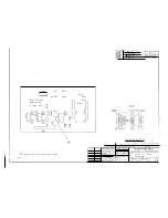
this signal turns off, possibly due to a soft CPU error, timer Ul09
times out and resets the CPU. Pin 40 is the Real Time Clock (RTC)
input. The CPU uses this signal for all timing, including display
multiplexing.
U107 interfaces the CPU to the display board. 1109 extends the CPU
bus to the option boards, and may not be used in all installations.
Analog signals enter the board on J301. D301-306 provide protection
to high impedance input stages. Since voltage is measured as the
difference between HV and ILOW, U301-303 form an instrumentation
amplifier that measures it. U303 output is buffered by U310 and
output on the rear panel. Output current is buffered by U309.
Analog inputs (IHIGH, ILOW, and HV) are selected by the CPU using
dialectically isolated analog switches. The selected signal is directed
to variable gain amplifier U304. The CPU can select gains of 1, 10, or
100 by turning the appropriate analog switches on or off. U305 and
U306 form an automatic polarity circuit. No matter what the input
polarity, the output is positive with a gain of one.
This signal is then digitized by the 8-bit, successive approximation,
AID
converter U308. D307 and U307 form an adjustable -3.06V
reference. The microprocessor continuously samples both current and
voltage, alternately. Gain in the voltage mode is always one. In
current mode, the CPU selects IHIGH or ILOW and gains of 1, 10, or
100 to provide an appropriate level signal for the
AID
converter.
5.5
Display Board (Schematic 1003223)
The display board contains all LED drivers and the keyboard interface.
All LEDs (except DS213-216) and the keyboard are multiplexed.
These are driven from 4/6 U205 because of their high current
requirement. The multiplexed array consists ofDS201-212 and
DS701-703 on the keyboard. The scanning sequence places the digit
number on U203 input, which is decoded to an individual digit select
line. This signal then drives U204 and 1/6 U205, which provides
buffering and current sink for the selected digit. The segment
information is then placed on the inputs to U201-202. These devices
provide the drive current for the selected LED. After 3.3 ms, the drive
is shut off, the next digit is selected, and the process is repeated. The
entire array is scanned in 23 ms. Because of the slow response time of
the human eye, it appears that all LEDs are lit simultaneously.
Theory of Operation
5-3


