background image

_____________________________________________________________________________________________________________________ 

                                                                                                                                                     CLEER Switch – Quick Install Guide                                                                                                                           8 

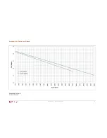
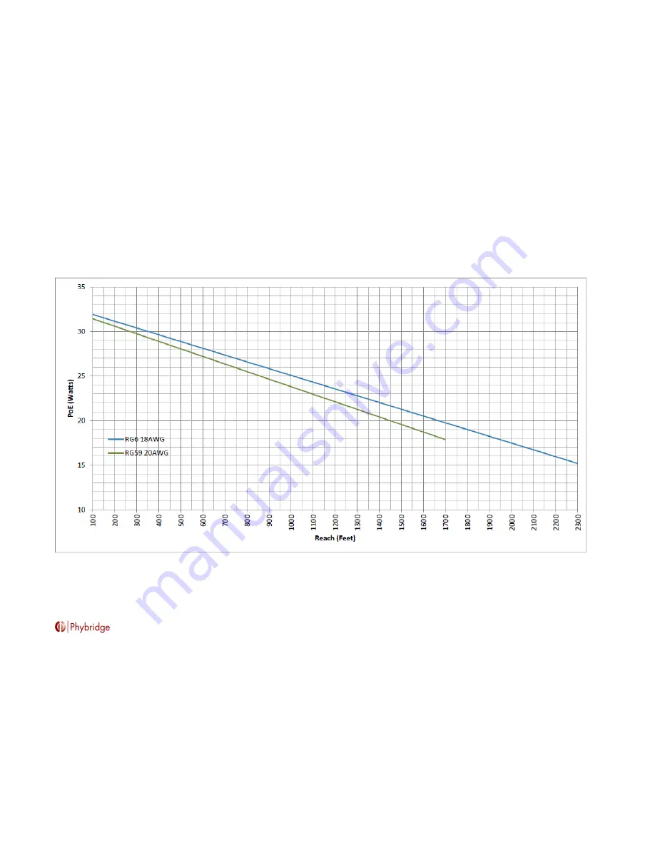
Appendix A: Power vs. Reach 


P/N: 8009-02-01 Rev. C 
Printed in Canada 

Содержание CLEER24

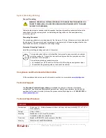
Страница 1: ...ns The ground symbol within a circle identifies the terminal to be connected to an external protective conductor Connect this terminal to earth ground before you make any other connections to the equipment Location and Regional Specifications The CLEER24 can be installed in any indoor location in all countries except in Finland Norway and Sweden where in these 3 Nordic countries it must be install...

Страница 2: ...following items are available before you begin The CLEER24 switch and all cables and accessories you received in the CLEER package All EC Links required for connecting the IP endpoint devices provided with the product package according to the quantity ordered SFP transceiver modules for the Gbic uplink trunks available if connecting over fiber Fiber optic LAN cables for the Gbic uplink trunks user...

Страница 3: ... Considerations CLEER24 switches come standard with hot swappable PowerWise power supply for power load sharing The switch will support either AC or DC power source The switches are amongst the lowest power consuming switches in the industry For a redundant power configuration daisy chain multiple CLEER24 switches You can connect up to a max of 4 units for power load sharing Mount all CLEER24 swit...

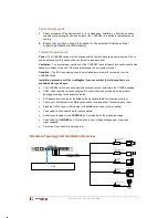
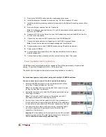
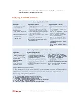
Страница 4: ...le cable connected directly to the console port Console Port Serial Settings 115200 8 N 1 Default User Name Password User Name admin Password admin Connect to the console port 1 Connect the RJ45 end of the serial cable to the console port of the CLEER24 Connect the serial end of the serial cable to the serial port of your PC 2 Configure your serial port to 115200 8 N 1 3 Login is admin password is...

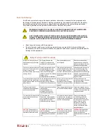
Страница 5: ...ation avant de réparer l unité Esta unidad puede tener más de una entrada de energía Para reducir el riesgo de peligro de descargas eléctricas o descargas eléctricas desconecte todas las entradas de alimentación antes de reparar la unidad To ensure adequate cooling of the equipment a 2 inch unobstructed space must be provided around all sides of the unit Um die Kühlung des Gerätes nicht zu beeintr...

Страница 6: ...fies the terminal to be connected to an external protective conductor Connect this terminal to earth ground before you make any other connections to the equipment The protective grounding conductor must be An Insulated wire 5 13mm2 to 14 2mm2 AWG with green and yellow stripes Connected to the grounding stud on the back of the cabinet Compliance and Environmental information All the compliance and ...

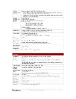
Страница 7: ...upply Unit Autosensing 100 240VAC 50 60 Hz Power output 500W max at 100VAC 1000W max at 240VAC Power consumption 16 5W Power injection PoE DC voltage 48VDC to 56VDC Endpoint devices must be compliant with IEEE 802 3af at PowerWISE power sharing 2 male connectors rear DC IN and DC OUT 48VDV to 56VDC Operating temperature 10 C to 50 C Humidity 10 to 95 non condensing at 35 C EC Link Dimensions 2 1cm...

Страница 8: ..._____________________________________________________________________________________________________________ CLEER Switch Quick Install Guide 8 Appendix A Power vs Reach P N 8009 02 01 Rev C Printed in Canada ...

Отзывы: