


6
Hardware Interface
6.1
Connectors
6.1.1
CameraLink
®
Connector
The CameraLink
®
cameras are interfaced to external components via
•
a CameraLink
®
connector, which is defined by the CameraLink
®
standard as a 26 pin, 0.5"
Mini Delta-Ribbon (MDR) connector to transmit configuration, image data and trigger.
•
a subminiature connector for the power supply, 7-pin Binder series 712.
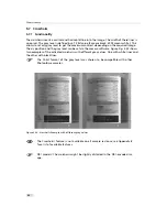
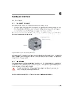
The connectors are located on the back of the camera. Fig. 6.1 shows the plugs and the status
LED which indicates camera operation.
Figure 6.1: Rear view of the CameraLink camera
The CameraLink
®
interface and connector are specified in [CL]. For further details including the
pinout please refer to Appendix Appendix A. This connector is used to transmit configuration,
image data and trigger signals.
6.1.2
Power Supply
The camera requires a single voltage input (see Table 4.5). The camera meets all performance
specifications using standard switching power supplies, although well-regulated linear power
supplies provide optimum performance.
It is extremely important that you apply the appropriate voltages to your camera.
Incorrect voltages will damage the camera.
For further details including the pinout please refer to Appendix Appendix A.
.
65
Содержание D-2048 CameraLink Series
Страница 1: ...User Manual Photonfocus D L 2048 CameraLink Series CMOS Area Scan Camera MAN054 11 2013 V1 3...
Страница 2: ......
Страница 4: ...2...
Страница 8: ...CONTENTS 6...
Страница 16: ...3 How to get started CameraLink Figure 3 4 PFRemote start window 14...
Страница 92: ...8 Graphical User Interface GUI 90...
Страница 94: ...9 Mechanical Considerations 92...
Страница 96: ...10 Warranty 94...
Страница 98: ...11 References 96...
Страница 102: ...A Pinouts 100...
Страница 108: ...B Camera Revisions 106...


