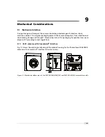
Photon Focus D-2048 CameraLink Series Скачать руководство пользователя страница 103

B

Camera Revisions

B.1

General Remarks

This chapter lists differences between the revisions of the camera models.

List of terms used in this chapter:

Status Line V1.0

Status line fields up to start pixel 76 (FineGain). Values are sampled at the

time when the status line is inserted.

Status Line V1.1

All fields of Status Line V1.0 plus additional field

Trigger Level

. Values are

sampled at the start of exposure.

Counter Reset External

Reset of image counter and real time counter by an external signal.

101

Содержание D-2048 CameraLink Series

Страница 1: ...User Manual Photonfocus D L 2048 CameraLink Series CMOS Area Scan Camera MAN054 11 2013 V1 3...

Страница 2: ......

Страница 3: ...responsibility is assumed by Photonfocus AG for its use Photonfocus AG reserves the right to make changes to this information without notice Reproduction of this manual in whole or in part by any mean...

Страница 4: ...2...

Страница 5: ...Functionality 25 5 1 Reduction of Image Size 25 5 1 1 Region of Interest ROI 25 5 1 2 Line Scan Mode L cameras only 27 5 1 3 Multiple Regions of Interest 28 5 1 4 Decimation monochrome cameras 31 5 1...

Страница 6: ...gger and Strobe Signals 66 6 1 4 Status Indicator CameraLink cameras 67 6 1 5 CameraLink Data Interface 67 7 The PFRemote Control Tool 69 7 1 Overview 69 7 2 PFRemote and PFLib 69 7 3 Operating System...

Страница 7: ...97 A 1 Power Supply Connector 97 A 2 CameraLink Connector 98 B Camera Revisions 101 B 1 General Remarks 101 B 2 2MP Area Scan Cameras 102 B 3 4MP Area Scan Cameras Speedgrade 160 102 B 4 4MP Area Scan...

Страница 8: ...CONTENTS 6...

Страница 9: ...egree of quality 1 2 Contact Photonfocus AG Bahnhofplatz 10 CH 8853 Lachen SZ Switzerland Sales Phone 41 55 451 00 00 Email sales photonfocus com Support Phone 41 55 451 00 00 Email support photonfocu...

Страница 10: ...ving been obtained from Photonfocus AG Photonfocus can not be held responsible for any technical or typographical er rors 1 5 Legend In this documentation the reader s attention is drawn to the follow...

Страница 11: ...r t y p e o p t i o n a l C a m e r a s p e e d I n t e r f a c e t y p e I n t e r f a c e r e s o l u t i o n Figure 2 1 Camera naming convention Prefix1 All cameras covered in this manual have MV1...

Страница 12: ...our sensor Name Resolution Camera Family Abbreviation NIR Color MV1 D2048x1088 160 CL 10 2 MPix D camera D 160 no no MV1 D2048x1088I 160 CL 10 2 MPix D camera D 160 yes no MV1 D2048x1088C 160 CL 10 2...

Страница 13: ...lity of the system CameraLink cables can be purchased from directly Photonfocus www photonfocus com in some countries A suitable power supply A suitable power supply can be purchased at your Photonfoc...

Страница 14: ...th a suitable CameraLink cable see Fig 3 2 Figure 3 2 Camera with frame grabber power supply and cable Do not connect or disconnect the CameraLink cable while camera power is on For more information a...

Страница 15: ...rsion of PFRemote on the support page at www photonfocus com 9 Install the camera software PFRemote Please follow the instructions of the PFRemote setup wizard Figure 3 3 Screen shot PFremote setup wi...

Страница 16: ...3 How to get started CameraLink Figure 3 4 PFRemote start window 14...

Страница 17: ...hutter correlated double sampling CDS in the pixel Micro lenses Colour cameras Bayer pattern filter and cut off filter 660nm CameraLink base interface Frame rates of the D 160 camera series 37 fps 204...

Страница 18: ...nterface Trigger External opto isolated trigger input Image pre processing 2 look up tables 12 to 8 bit on user defined image region Region LUT Features Greyscale colour resolution 10 1 bit 8 bit Regi...

Страница 19: ...60 CL 10 2048 x 2048 37 fps 1 no no no MV1 D2048I 160 CL 10 2048 x 2048 37 fps 1 yes no no MV1 D2048C 160 CL 10 2048 x 2048 37 fps 1 no yes no MV1 D2048 240 CL 8 2046 x 2048 45 fps 1 no no no MV1 D204...

Страница 20: ...ty 5 56 V lux s with micro lenses 550 nm Optical fill factor 42 without micro lenses Dark current 125 e s 25 C Dynamic range 60 dB Micro lenses Yes Colour format C cameras RGB Bayer Raw Data Pattern C...

Страница 21: ...075 LSB e Sensitivity 5 56 V lux s with micro lenses 550 nm Optical fill factor 42 without micro lenses Dark current 125 e s 25 C Dynamic range 60 dB Micro lenses Yes Colour format C cameras RGB Baye...

Страница 22: ...mm3 Mass 215 g Conformity RoHS WEEE Table 4 5 Physical characteristics and operating range Fig 4 2 shows the quantum efficiency curve of the monochrome CMV2000 4000 sensors from CMOSIS measured in th...

Страница 23: ...color spectral reponse Figure 4 3 Spectral response of the CMV2000 4000 CMOS colour image sensors with micro lenses The cover glass of the CMV2000 4000 image sensors is plain D263 glass with a transm...

Страница 24: ...er Pattern Filter Fig 4 6 shows the bayer filter arrangement on the pixel matrix in the colour camera models which is often denoted as Green Blue pattern The fixed bayer pattern arrangement has to be...

Страница 25: ...512 width 1024 3 width 1024 4 width 640 5 640 width 1280 6 width 1280 CameraLink port and bit assignments are compliant with the CameraLink standard see CL Table 4 7 shows the tap configurations for t...

Страница 26: ...ck cycle in parallel The framegrabber in 24 bit RGB mode however processes these 3 pixels as one RGB pixel In the RGB mode the memory management of a 24bit colour image has to be considered Blue is us...

Страница 27: ...W and height H The ROI width must be a multiple of 2 in the D 160 and L 160 cameras and a multiple of 6 in the D 240 cameras A list of common image dimension and its frame rates is shown in Table 5 1...

Страница 28: ...rates of different ROI settings for L 160 cameras minimal exposure time Footnotes 1 line scan mode EnLinescanHighSpeedMode must be set F r a m e R a t e f p s w i d t h F r a m e R a t e w i t h H 1 0...

Страница 29: ...n NrOfFrames into one frame In some cases it consumes less CPU power to process these combined frames than to process every frame individually There exist possibilities to transmit the combined frame...

Страница 30: ...number of rows and columns being read out Overlapping ROIs are not allowed and no row must be read out more than once The individual ROI in a MROI must not overlap and no row should be included in mo...

Страница 31: ...R O I X R O I W R O I Y R O I H R O I X R O I W M R O I 0 Y M R O I 0 H M R O I 1 Y M R O I 1 H M R O I 2 Y M R O I 2 H 0 0 R O I W M R O I 0 H M R O I 1 H M R O I 2 H 0 0 R O I W R O I H Figure 5 3...

Страница 32: ...need to be readout and a frame rate of 5598 fps D 240 can be achieved Without using MROI the resulting frame rate would be 338 fps for a 636x1088 ROI D 240 6 3 6 p i x e l 0 0 x m a x y m a x 2 0 p i...

Страница 33: ...he height of every ROI should be a multiple of 3 Fig 5 6 shows decimation on the full image The rows that will be read out are marked by red lines Row 0 is read out and then every nth row 0 0 x m a x...

Страница 34: ...5 Functionality 0 0 x m a x y m a x R O I Figure 5 7 Decimation and ROI M R O I 0 R O I M R O I 2 M R O I 1 0 0 x m a x y m a x Figure 5 8 Decimation and MROI 32...

Страница 35: ...tion of an injection needle is given in Fig 5 10 In this application the height information is less important than the width information Applying decimation 2 on the original image on the left hand si...

Страница 36: ...ows is the sum of the red rows The number of skipped rows for decimation d are Hskip d 1 2 The resulting number or rows for Window H h htot 2 floor h d min h mod 2 d 2 The total number of rows can be...

Страница 37: ...of the Photonfocus web page www photonfocus com The maximal frame rate with the current camera settings can be read out by a camera register with pflib and it is also displayed in the PFRemote tool T...

Страница 38: ...a d o u t F r a m e n F r a m e n 1 E x p o s u r e T i m e R e a d o u t T i m e T R e a d o u t D e l Figure 5 12 Simultaneous read out timing 1 exposure time smaller than read out time Simultaneous...

Страница 39: ...mera I O Trigger see Section 5 2 2 The trigger signal can be configured to be active high or active low When the frequency of the incoming triggers is higher than the maximal frame rate of the current...

Страница 40: ...f the I O trigger input and the strobe output is described in Section 6 1 3 C a m e r a S y s t e m P C M a c h i n e V i s i o n B A D a t a C a m e r a L i n k P o w e r E X S Y N C C C 1 S o f t t...

Страница 41: ...camera environment to allow robust integration of the camera into the vision system In the signal isolator the trigger signal is delayed by time td iso input This signal is clocked into the FPGA whic...

Страница 42: ...arts the camera states machine which controls the sensor The falling edge of the trigger pulse stops the image acquisition Additionally the optional external strobe output is controlled by the rising...

Страница 43: ...rigger edge and the start of the exposure This feature may be required to synchronize to external strobe with the exposure of the camera 5 2 5 Burst Trigger The camera includes a burst trigger engine...

Страница 44: ...t e r n a l s t r o b e p u l s e o u t p u t t d i s o i n p u t t j i t t e r t t r i g g e r d e l a y t e x p o s u r e t s t r o b e d e l a y t d i s o o u t p u t t s t r o b e d u r a t i o n...

Страница 45: ...gger offset non burst mode 100 ns duration of 1 row ttrigger offset burst mode 125 ns 125 ns texposure 15 s 1 28 s 0 42 s tstrobe delay 0 0 42 s tstrobe offset non burst mode 100 ns 100 ns tstrobe off...

Страница 46: ...2 ns duration of 1 row ttrigger offset burst mode 104 ns 104 ns texposure 13 s 1 26 s 0 35 s tstrobe delay 0 0 35 s tstrobe offset non burst mode 83 2 ns 83 2 ns tstrobe offset burst mode 104 ns 104 n...

Страница 47: ...ssed Trigger Counter reaches its maximal value it will not wrap around The user can reset the Missed Burst Trigger Counter 5 2 9 Counter Reset by an External Signal The image counter and the real time...

Страница 48: ...time If this is an issue then the counters could be reset periodically by the external signal The counter reset by an external signal feature is not available on all camera revisions see Appendix B f...

Страница 49: ...Vlow1 the higher the value the higher the compression Multislope_Time1 Time corresponding to kneepoint B The value is the fraction per mill of the total exposure time Multislope_Value2 Corresponds to...

Страница 50: ...r e s e t K n e e p o i n t A K n e e p o i n t B M u l t i s l o p e _ T i m e 2 M u l t i s l o p e _ T i m e 1 E x p o s u r e T i m e Figure 5 21 Multi Slope HDR mode n u m b e r o f e l e c t r o...

Страница 51: ...f available features Output data resolution is fixed to 8 bit in DR1 and D 240 camera models I m a g e S e n s o r D i g i t a l O f f s e t D i g i t a l G a i n L o o k u p t a b l e L U T C r o s s...

Страница 52: ...nd if the brightness of the image is too big then the interesting part of the output image might be saturated By subtracting an offset from the input of the gain block it is possible to avoid the satu...

Страница 53: ...ves 5 6 1 Gain The Gain mode performs a digital linear amplification with clamping see Fig 5 25 It is configurable in the range from 1 0 to 4 0 e g 1 234 0 200 400 600 800 1000 1200 0 50 100 150 200 2...

Страница 54: ...onitor screens 0 200 400 600 800 1000 1200 0 50 100 150 200 250 300 Grey level transformation Gamma y 255 1023 x 1 x grey level input value 10 bit DN y grey level output value 8 bit DN 1 0 1 2 1 5 1 8...

Страница 55: ...tive on whole image X LUT 1 is active on whole image X X LUT 0 active in Region 0 X X X LUT 0 active in Region 0 and LUT 1 active in Region 1 LUT 0 supersedes LUT1 Table 5 10 LUT Enable and Region LUT...

Страница 56: ...a x y m a x L U T 1 x 0 0 x 1 0 x 0 1 x 1 1 y 1 0 y 0 0 y 0 1 y 1 1 Figure 5 29 Overlapping Region LUT example L U T 0 L U T 1 L U T 1 L U T 0 0 0 0 0 x m a x y m a x x m a x y m a x Figure 5 30 Regi...

Страница 57: ...of the application of the Region LUT is shown on the right hand side One Region LUT was applied on a small region on the lower part of the image where the brightness has been increased Figure 5 31 Reg...

Страница 58: ...and the grey level can be set via the camera software Figure Fig 5 32 shows two examples of the activated crosshairs with different grey values One with white lines and the other with black lines The...

Страница 59: ...ons The crosshairs however is set differently The crosshairs is not seen in the image on the right because the x and y position is set outside the MROI region 0 0 x a b s o l u t y a b s o l u t G r e...

Страница 60: ...r width 8 bit no wrap around see also Section 5 2 8 Missed burst trigger counter When the camera is in burst trigger mode see Section 5 2 5 a missed burst trigger counter will be incremented when a su...

Страница 61: ...ndow Y In MROI mode this parameter is the start position of the first ROI 44 11 Number of rows 1 48 2 Trigger Source 52 2 Digital Gain 56 2 Digital Offset 60 16 Camera Type Code see Table 5 12 64 32 C...

Страница 62: ...048x1088C 160 CL 10 412 MV1 D2048x1088 240 CL 8 403 MV1 D2048x1088I 240 CL 8 TBD MV1 D2048 160 CL 10 452 MV1 D2048I 160 CL 10 453 MV1 D2048C 160 CL 10 454 MV1 D2048 240 CL 8 458 MV1 D2048I 240 CL 8 TB...

Страница 63: ...SR linear feedback shift register test image outputs a constant pattern with a pseudo random grey level sequence containing every possible grey level that is repeated for every row The LFSR test patte...

Страница 64: ...ame grabber A possible origin of failure message can be caused by the CameraLink cable which exceeds the maximum length The maximal cable length depends on the frequency of the pixel clock At a pixel...

Страница 65: ...sion errors CameraLink cables contain wire pairs which are twisted in such a way that the cable impedance matches with the LVDS driver and receiver impedance Excess stress on the cable results in tran...

Страница 66: ...accessible Instead the serial communication is usually routed through the frame grabber For some frame grabbers it might be necessary to connect a serial cable from the frame grabber to the serial int...

Страница 67: ...6 1 Rear view of the CameraLink camera The CameraLink interface and connector are specified in CL For further details including the pinout please refer to Appendix Appendix A This connector is used t...

Страница 68: ...id damage to the internal ESD protection and the optocoupler In order to use the strobe output the internal optocoupler must be powered with 5 15 V DC The STROBE signal is an open collector output the...

Страница 69: ...the serial communication Data signals CameraLink data signals contain the image data In addition handshaking signals such as FVAL LVAL and DVAL are transmitted over the same physical channel Camera c...

Страница 70: ...i x e l C l o c k C C S i g n a l s S e r i a l I n t e r f a c e F r a m e g r a b b e r C a m e r a L i n k Figure 6 3 CameraLink interface system The frame grabber needs to be configured with the p...

Страница 71: ...n image use the software or the SDK that was delivered with your frame grabber Figure 7 1 PFRemote and PFLib in context with the CameraLink frame grabber software 7 3 Operating System The PFRemote GUI...

Страница 72: ...a main window Fig 7 2 and a configuration dialog In the main window the camera port can be opened or closed and log messages are displayed at the bottom The configuration dialog appears as a sub windo...

Страница 73: ...rename it to clser dll The PortBrowser will then indicate this DLL as clser dll at PFRemote directory After connecting the camera the device can be opened with a double click on the port name or by ri...

Страница 74: ...Reset Reset camera and reset the configuration to the factory defaults 7 6 Device Properties Cameras or sensor devices are generally addressed as device in this software These devices have properties...

Страница 75: ...D2048 x1088 I 240 CL CameraLink interface MV1 D2048 x1088 C 160 CL CameraLink interface MV1 D2048 x1088 C 240 CL CameraLink interface The following sections are grouped according to the tabs in the c...

Страница 76: ...hus fewer images can be acquired than would otherwise be possible When Constant Frame Rate is switched off the camera delivers images as fast as possible depending on the exposure time and the read ou...

Страница 77: ...inate starting from 0 in the upper left corner Y Y coordinate starting from 0 in the upper left corner W Window width in steps of 2 pixel H Window height Set to max ROI Set Window to maximal ROI X 0 Y...

Страница 78: ...s starting value in y direction and its height The width and the horizontal offset are specified by X and W settings The maximum frame rate in MROI mode depends on the number of rows and columns being...

Страница 79: ...respectively I O Trigger The trigger signal is applied directly to the camera on the power supply connector Exposure time defined by Camera The exposure time is defined by the property ExposureTime Tr...

Страница 80: ...ut signal Number of Burst Triggers Set the number of burst Burst Trigger Period ms Set the time between the burst in milliseconds Burst Trigger Delay ms Set the delay of the burst trigger in milliseco...

Страница 81: ...Test image Linear feedback shift register pseudo random image The pattern depends on the grey level resolution Ramp Test image Values of pixel are incremented by 1 starting at each row The pattern dep...

Страница 82: ...o adjust the brightness of the whole image in small steps Color Color models only There is additionally a gain for every color channel The color fine gain is used to calibrate the white balance in an...

Страница 83: ...on the grey level resolution Ramp Test image Values of pixel are incremented by 1 starting at each row The pattern depends on the grey level resolution Resolution 8 Bit Grey level resolution of 8 bit...

Страница 84: ...g gain 1 2x 1 4x Analog gain 1 4x 1 6x Analog gain 1 6x Fine Gain The fine gain can be used to adjust the brightness of the whole image in small steps Enable BGR Enable BGR Swap Tap0 and Tap2 if the f...

Страница 85: ...ut grey levels 0 to 4096 and 0 to 255 This camera support 2 LUT both are identical The default LUTs is a gain function with value 1 LUT0 has higher priority as LUT1 Both LUT can be configured with the...

Страница 86: ...eps of 2 pixel H Region LUT window height Set to max ROI Set Region LUT window to maximal ROI X 0 Y 0 W 2080 H 2080 LUT Files To load or save a LUT file LUT Index Select the LUT you want to load or sa...

Страница 87: ...adjusted 2 times within one exposure time to achieve a maximum of 3 slopes in the response curve There are 3 predefined Multislope settings available Alternatively custom settings can be defined in t...

Страница 88: ...t in this mode The number of rows and their position can be set in the Region Of Interest setting in the Window panel as usual More advanced settings such as Decimation or MROI are supported in this m...

Страница 89: ...height setting Htot for the frame grabber is visible in the Window panel see Section 8 1 2 Enable Enable the FrameCombine mode Note that the FrameCombine mode is only available if EnLinescanHighSpeed...

Страница 90: ...8 10 Info panel Camera Info Camera name Name of the connected camera Typecode Type code of the connected camera Serial Serial number of the connected camera FPGA Revision Firmware revision of built in...

Страница 91: ...ime counter timestamp to be reset by an external signal The Reset Counters feature is not available in all camera revisions Mode Reset Counters mode It determines how often the selected source should...

Страница 92: ...8 Graphical User Interface GUI 90...

Страница 93: ...and transport Please either retain this packaging for possible later use or dispose of it according to local regulations 9 1 1 MV1 cameras with CameraLink Interface Fig 9 1 shows the mechanical drawin...

Страница 94: ...9 Mechanical Considerations 92...

Страница 95: ...the manufacturer and accompanying said product and the product shall be free from defects in materials and workmanship under normal use The distributor shall not make or pass on to any party any warr...

Страница 96: ...10 Warranty 94...

Страница 97: ...amera Acquisition Modes Photonfocus March 2004 AN008 Application Note Photometry versus Radiometry Photonfocus December 2004 AN010 Application Note Camera Clock Concepts Photonfocus July 2004 AN021 Ap...

Страница 98: ...11 References 96...

Страница 99: ...he pin assignment of the power supply plug is given in Table A 2 It is extremely important that you apply the appropriate voltages to your camera Incorrect voltages will damage or destroy the camera F...

Страница 100: ...isolated strobe signal Table A 2 Power supply plug pin assignment A 2 CameraLink Connector The pinout for the CameraLink 26 pin 0 5 Mini D Ribbon MDR connector is according to the CameraLink standard...

Страница 101: ...Positive LVDS Input Camera Control 4 CC4 13 PW SHIELD Shield 14 PW SHIELD Shield 15 O P_XD0 Positive LVDS Output CameraLink Data D0 16 O P_XD1 Positive LVDS Output CameraLink Data D1 17 O P_XD2 Posit...

Страница 102: ...A Pinouts 100...

Страница 103: ...atus Line V1 0 Status line fields up to start pixel 76 FineGain Values are sampled at the time when the status line is inserted Status Line V1 1 All fields of Status Line V1 0 plus additional field Tr...

Страница 104: ...yes Line Scan Mode no no no Frame Combine no no no MROI yes yes yes Decimation yes yes yes Standard Trigger yes yes yes Counter Reset External no no no Multiple Slope yes yes yes Column FPN Correction...

Страница 105: ...ombine no no MROI yes yes Decimation yes yes Standard Trigger yes yes Counter Reset External no yes Multiple Slope yes yes Column FPN Correction no yes Digital Gain Offset yes yes Analog Gain yes yes...

Страница 106: ...ame Combine no no MROI yes yes Decimation yes yes Standard Trigger yes yes Counter Reset External no yes Multiple Slope yes yes Column FPN Correction no yes Digital Gain Offset yes yes Analog Gain yes...

Страница 107: ...rame Combine yes yes MROI yes yes Decimation yes yes Standard Trigger yes yes Counter Reset External no yes Multiple Slope yes yes Column FPN Correction no yes Digital Gain Offset yes yes Analog Gain...

Страница 108: ...B Camera Revisions 106...

Страница 109: ...V1 D2048 x1088 I C 240 W 2 W0 MV1 L2048 I C camera series added Minimal exposure time corrected Chapter Introduction added and abbreviated camera names used in the manual 1 3 November 2013 Minimal exp...

Отзывы: