background image


boot-up.  You do not need to make changes to this field.  This is a display onl

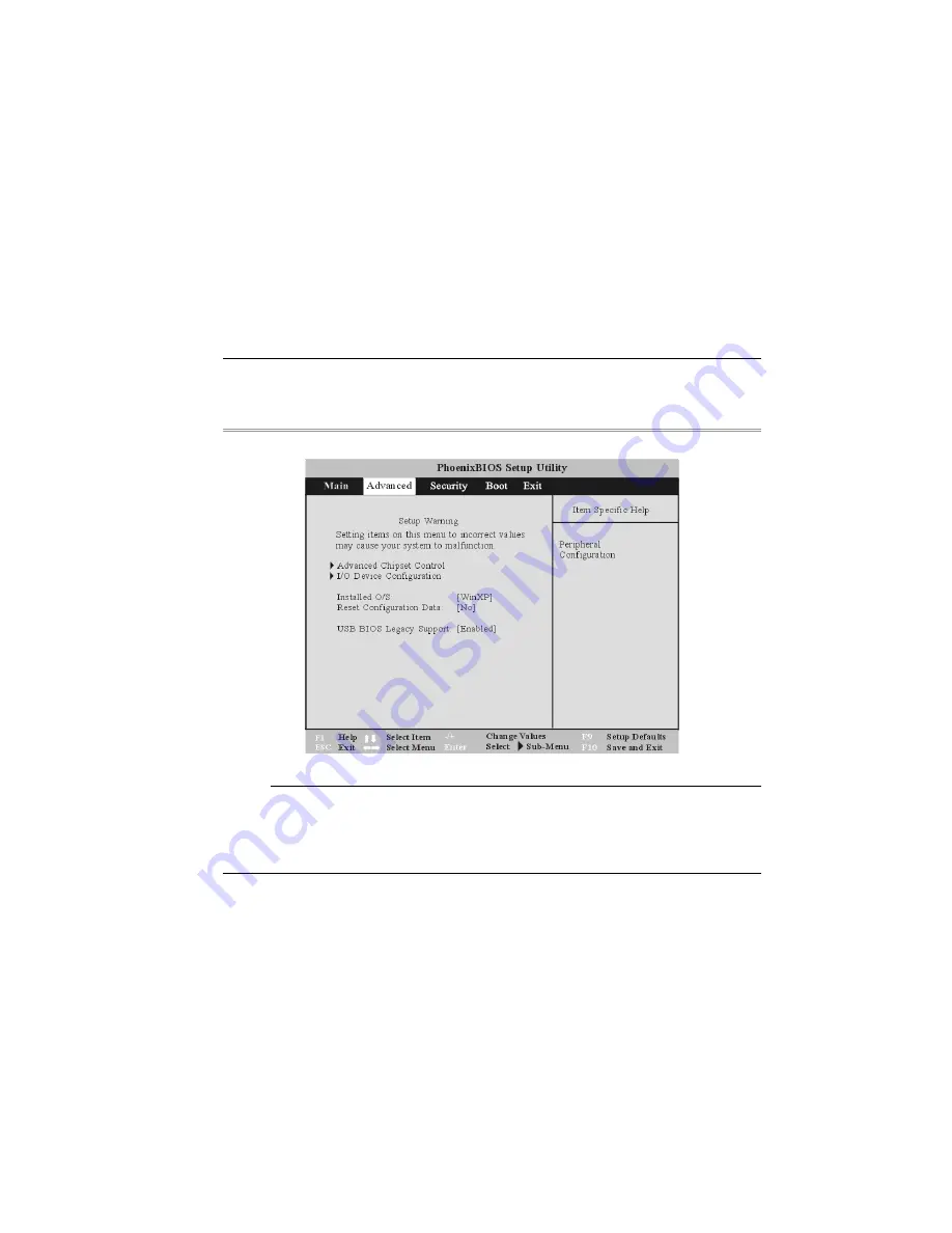
Advanced

 from the menu bar displays the advanced menu: 

y field. 

The Advanced Menu 

Selecting 


`


I/O Device Configuration 

This menu 
as well as th

below. 

allows you to configure the notebook's serial and parallel ports diskette controller 

e peripherals connected to your system. Each field on this submenu is covere

54 

Содержание Notebook Computer

Страница 1: ...User s Guide Notebook Computer ...

Страница 2: ......

Страница 3: ...ns in any form without prior written permission of the manufacturer Trademarks Phoenix is a trademark of Phoenix BIOS Corporation AutoCAD and Autoshade are trademarks of Autodesk Inc IBM OS 2 and VGA are trademarks of International Business Machines Corp Lotus 1 2 3 and Symphony are trademarks of Lotus Development Corp Windows Word MS DOS and Microsoft are trademarks of Microsoft Corp VESA is a tr...

Страница 4: ... no guarantee that interference will not occur in a particular installation If this equipment does cause harmful interference to radio or television reception which can be determined by turning the equipment off and on the user is encouraged to try to correct the interference by one or more of the following measures Reorient or relocate the receiving antenna Increase the separation between the equ...

Страница 5: ...nsafe conditions while working with this product Required safety features have been installed in the computer to protect you from injury However you should use good judgment to identify potential safety hazards 1 2 3 4 5 6 7 Please read these safety instructions carefully Please keep this User s Manual for later reference Please disconnect this equipment from AC outlet before cleaning Don t use li...

Страница 6: ...ersonnel The Power cord or plug is damaged Liquid has penetrated into the equipment The equipment has been exposed to moisture The equipment has not worked well or you cannot get it work according to the user s manual The equipment has dropped and damaged If the equipment has obvious sign of breakage Do not leave this equipment in an environment unconditioned storage temperature above 60 C 140 f i...

Страница 7: ... The flexible cord must be of a HAR harmonized type H05VV F The cord set must have a current capacity of a least 2 5 Amperes and voltage rating of 125 or 250 Vac When using your telephone equipment basic safety precautions should always be followed to reduce the risk of fire electric shock and injury to persons These precautions includes the following 1 Do not use this product near water for examp...

Страница 8: ...ersenden Sie Keine Flüssig oder Aerosolreiniger Am besten eignet sich ein angefeuchtetes Tuch zur Reinigung Die Netzanschluβsteckdose soll nahe dem Gerät angebracht und leicht zugänglich sein Das Gerät ist vor Feuchtigkeit zu schützen Bei der Aufstellung des Gerätes ist auf sicheren Stand zu achten Ein Kippen oder Fallen könnte Beschädigungen hervorrufen Beachten Sie beim Anschluß an das Stromnet ...

Страница 9: ...r das Gehäuse ist beschädigt Wenn das Gerät deutliche Anzeichen eines Defektes aufweist VORSICHT Explosiongsgetahr bei unsachgemäßen Austausch der Batterie Ersatz nur durch denselben oder einem vom Hersteller empfohlenem ähnlichen Typ Entsorgung gebrauchter Batterien nach Angaben des Herstellers Dieses Schaltnetzteil kann bis zu einer Außentemperatur von maximal 35ºC Die Ausgangswerte dürfen nicht...

Страница 10: ...rätes sollten Sie immer die grundlegenden Sicherheitsmaßnahmen beachten um das Risiko von Feuer Stromschlägen und Verletzungen zu minimieren Zu beachten sind u a folgende Punkte 1 Benutzen Sie das Gerät nicht in der Nähe von Wasser wie zum Beispiel Badewanne Waschbecken Spülbecken Waschbottich in feuchten Kellerräumen oder in der Nähe von Schwimmbecken 2 Benutzen Sie kein Telefon ausgenommen schnu...

Страница 11: ... des Herstellers Entfernen Sie den Akku auf keinen Fall bei eingeschaltetem Notebook da hierdurch Daten verloren gehen könnten Personal Inventory This Notebook computer system is designed for years of productive and pleasurable computing Use this section to keep notes about details of your purchase Update this section when you add new options Date of Purchase Dealer s Name Phone Address E Mail Add...

Страница 12: ......

Страница 13: ...Introduction 1 ...

Страница 14: ...ittle glare from the sun on the monitor Walk around the room every hour Every half hour look away from the computer screen for a few minutes Place everything that you need to work within easy reach Welcome to the Notebook PC Congratulations on your purchase of the Notebook PC Your Notebook features the latest advances in portable computing technology The Notebook s modular design provides maximum ...

Страница 15: ...cks the display in closed position when the Notebook is not in use 1 Pull up the two external speaker at both sides to make it adjacent to the LCD panel 2 3 4 Raise the LCD panel At any time you can tilt the display toward or away from you to a comfortable viewing position To close the LCD panel raise down the panel then pull down the two external speaker 3 ...

Страница 16: ...pon closing it 2 Try not to place any object on top when it is closed or open 3 Be sure the system is turned off or in suspend mode before you close the display panel With the LCD screen open you will see several features important for operating your Notebook computer 4 ...

Страница 17: ...Each of these features is briefly described below 5 ...

Страница 18: ...ide a true stereo sound for your system Short cut Keys These two short cut keys are assigned as functions for Explorer and mail respectively Internet Explorer Button 1 2 4 Use this key to open the Internet Explorer Outlook Express Button Use this key to open Microsoft s Outlook to send receive your mail Power Resume Button Pressing this button for 1 2 seconds will turn on the system or pressing th...

Страница 19: ...The PS 2 compatible mouse will work with the Notebook PC s TouchPad simultaneously Scroll Button Use this button to scroll up and down the scrolling bar The Built in Microphone The built in microphone is located to the left of the TouchPad System Status Indicator Panel The system status indicator panel keeps you informed of the computer s operating status There are also two system status indicator...

Страница 20: ...Caps Lock mode In this mode the keyboard produces uppercase text when you press a key When you press the Caps Lock key again the indicator goes off and the keyboard produces lowercase text Indicates when the keyboard is in Scroll Lock mode Some applications will move information across the screen differently when Scroll Lock is on The Front This application does not apply when the system is power ...

Страница 21: ...pped track the track restarts from its very beginning Press this button to open the disc tray The button then changes to Close waiting for you to change the disc and close the tray The Previous Track Button Press this button to start the previous track The Next Track Button Press this button to start the next track The Volume Buttons Press the left button to decrease the volume or the right button...

Страница 22: ...ening Please don t block this opening during operation of the system The LAN Port This jack provides a standard RJ 45 connection for integration with an existing network or a high speed ADSL or cable connection via a network cable 10 ...

Страница 23: ... data delivering data at a guaranteed rate This makes it ideal for devices that need to transfer high levels of data in real time such as video devices Also supports both Plug and Play and hot plugging and also provides power to peripheral devices PCMCIA Socket Cover Open this cover to access the PCMCIA socket The computer s PCMCIA socket lets you extend the capabilities of your computer by insert...

Страница 24: ...ry is in charging status It also indicates when the system enter suspend mode 2 Power On This indicator will lit when the notebook is powered on The Right Side 1 The DVD ROM or DVD Combo Your Notebook comes with a swappable 5 25 IDE 8X DVD ROM or 16X Combo drive 12 ...

Страница 25: ... The Rear 1 2 Audio Line Out SPDIF Jack You can plug an external speaker headphone or connect the line out jack to an audio device such as a cassette recorder to record the notebook s audio output S PDIF engine receives the digital format data from DVD ROM or Combo drive regroup the date to be synchronous signal and de multiplexes audio and other digital data External Microphone Jack This mono mic...

Страница 26: ...tional female port External CRT Port This port allows you to easily connect an external VGA SVGA display monitor into your Notebook using the 15 pin female connector TV Out Port This 4 pin S Video port allows you to view the Notebook s Video output on a television monitor The Modem Port This jack is an internal 56K voice fax data modem You will connect your computer to your phone line through this...

Страница 27: ...9 Ventilation Opening Please don t block this opening during operation of the system The Bottom Panel 15 ...

Страница 28: ... to release the battery from its bay Hard Disk Drive Your computer includes a 2 5 inch IDE hard disk drive 9 5mm in height The notebook PC s BIOS automatically detects IDE drive types DVD ROM Release Latch Push this latch to release the DVD ROM from its bay Expansion Compartment This compartment will serve as an expansion to upgrade your RAM module CPU Compartment This compartment will serve as up...

Страница 29: ...Getting Started 2 ...

Страница 30: ...tage can range anywhere from 100 to 240 volts covering the standard voltages available in almost every country The power cord for the AC adapter requires a three hole grounded AC outlet To connect the computer to an external power source 1 2 Plug the AC adapter s connector into the DC IN connector on the rear of the computer Connect the power cord to the AC adapter and then to a wall outlet 18 ...

Страница 31: ...on can damage the Notebook s electrical circuitry Turning On Your Notebook Computer Turn on your Notebook by pressing the power button Hold the button down for a second or two and release The Power On Self Test POST runs automatically After the POST is completed the computer reads the operating system from the hard disk drive into computer memory this is commonly referred to as booting a computer ...

Страница 32: ...the wrong battery could cause serious damage to your computer and yourself through toxic emissions Inserting and Removing the Battery Pack The battery pack should already be inserted in your Notebook computer when you unpack it If not inserted follow these directions 1 2 Turn over the notebook with the front of the unit facing you and place it on a solid flat surface Angle the battery into the bay...

Страница 33: ...e bay To remove the battery pack Turn off the notebook and disconnect the AC adapter Close the LCD panel and turn it over and place it on a solid flat surface Lift the release latch to release the battery from the bay At this time the battery will now be angled slightly out of the bay 21 ...

Страница 34: ...ing the Battery Pack The installed battery pack charges automatically any time the computer is connected to the AC adapter and an external power source If this is your first t fully discharge the fully charged ime to use the battery be sure to battery and recharged until it is 22 ...

Страница 35: ...Using the Noteboo k Computer 3 23 ...

Страница 36: ...jects directly rectly onto the display o not press on or store any objects on the cove original size Fn F12 This key combination toggles the display between the LCD CRT simultaneous LCD CRT TV simultaneous CRT TV LCD Care L careful handling Please pay attention to the fo the LCD screen closed to protect it from dust If you need to clean y soft tissue to gently wipe the LCD surface D on the surface...

Страница 37: ... an external essing the NumLock key on either the Notebook or external meric keypad while keeping the keypad on an external key use the Fn NumLk hot key on the Notebook keyboard s keyboard uses a standard QWERTY layout with the addition and an embedded numeric keypad for number intensive data ent pports Windows by incorporating the two Windows sp two Window timesaving fe The function keys F1 F12 o...

Страница 38: ...olume Fn F4 Increases the speaker volume Fn F7 Decreases the brightness level Fn F8 Increases the brightness level Fn F10 Use this key combination to expand your video screen or reset to its original size Fn F12 This key combination toggles the display between the LCD CRT simultaneous LCD CRT TV simultaneous CRT TV ouchPad The T The touchpad is a rectangular electronic panel located just below you...

Страница 39: ...ng precautions Make sure the TouchPad does not come into contact with dirt liquids or grease Do not touch the TouchPad if your fingers are dirty Do not rest heavy objects on the TouchPad or the TouchPad buttons You can use the TouchPad with Microsoft Windows as well as non Windows applications 27 ...

Страница 40: ...upgrades Combo when The DVD ROM Features of the DVD ROM Combo Module The features of the DVD ROM Combo drive are listed below The Audio Play feature allows you to play music CDs Front panel load unload button Supports CD DA DVD ROM mode 1 and mode 2 Multi Session Photo CD CD I Video CD pcs ns for Handling DVD ROM Combo Discs Low power consumption 12 7mm height Precautio Always hold the disc by the...

Страница 41: ...the center ring is not accessing the DVD pull the tray all the way out e DVD ROM Combo from the tray 3 Push the tray back into the drive To remove a disk do the following 1 Check the LED display and make sure that the computer ROM drive 2 Push the eject button and 3 Carefully pick up the CD disk by the edges and while pressing down on the center ring remove th D stretch a paper clip or use a pin o...

Страница 42: ...Removi g the DVD ROM Combo Drive n elease latch into the direction of the arrow as described in the illust 1 Push the r ration 30 ...

Страница 43: ...Pull out the DVD ROM drive from the bay k features one PCMCIA expansion socket design to interface with one 2 PCMCIA Cards and Expansion Sockets The Noteboo Type II card 31 ...

Страница 44: ...sh th the PCMCIA When inserting a Type II PC card make sure the connector is inserted in the socket Before ejec card ensure that it is not being accessed by the S For example if the message Write protect error wri Drive x is displayed the user has to change the wri protect switch setting on the memory card To cha the switch setting a eject the card b change switch setting and c re insert the card ...

Страница 45: ...puter on battery power for the first time check the battery status icon on the Windows To ee Battery St icon ate If poss us later in this section for a description and explanation of arging the battery takes about 3 hours to charge when the system is in always charge the battery completely e Battery Pack i attery pack from its compartment please refer to Chapter Two Inse he Battery Pack To remove ...

Страница 46: ...ning indicator appears and fully recharges the battery each time full discharge charge cycle will ensure the accurate reporting of the battery gauge status Automatic Battery Pack Charging Function You can automatically charge the battery pack by using the AC Adapter The charge time is about three hours when the Notebook power is turned off The following table summarizes the charging modes Charge M...

Страница 47: ...there is 7 to 10 minutes charge remaining Beeping accelerates Battery Low Low Indicates that there is 1 to 2 minutes of battery charge remaining Save your work and turn off the Notebook or connect the AC adapter When there is only one minute of battery charge remaining the Notebook will suspend to the HDD and power off You should connect AC power and resume to save your work S l Battery mal for th...

Страница 48: ...ent To reset the system or reboot press the Ctrl Alt Delete keys simultaneously This is known as warm boot This key combination acts as software reset switch when you encounter hardware or software problems which If this key combination does not shut down the Notebook you can reset the Notebook by using the Notebook s power button Should the Notebook lock up fo this but djusting the Br ness To adj...

Страница 49: ...4 Desktop Operation ...

Страница 50: ...dio capabilities allow you to take advantage of a wide range of education and entertainment multimedia software The Notebook is equipped with two internal stereo speakers a microphone and input audio ports for external audio units An External speakers or hea audio features are software controlled The Notebook s multimedia sound system includes the following features Supports Windows Sound System c...

Страница 51: ...Your system allows you to record sounds and store them as files using the microphone via the microphone jack on the rear of the notebook computer Check the Windows Help and Support Center in Windows for information on using the various elements in sound recording Control For a high quality sound click on the Volume Control at creen From the Volume windows click on the Advanced tab click and item t...

Страница 52: ...expand your computing capabilities you can add a variety of external devices to your computer You may for example want to add a mouse modem or a printer The computer is equipped wit printer port a serial port h several interface ports including an enhanced parallel and USB ports These are provided as a means of connecting e computer Connect peripheral devices to the computer s interface ports as s...

Страница 53: ...41 ...

Страница 54: ...42 ...

Страница 55: ...Running BIOS Setup 5 ...

Страница 56: ...ngs made in Notebook performs Navigating through the BIOS Setup program intimately affect how the BIOS Setup it as easy to use one to switch back us value The Setup program has been designed to make as possible If you accidentally make a setting and don t know which to the Setup program has a hot key that allows you to return to the previo Accessing the BIOS Setup Program To access the BIOS Setup ...

Страница 57: ...or left arrow key on the keyboard until the The Legend Bar controls access to the BIOS Boot Use this menu to c the Operating System Exit Use this menu to exit th program desired item is highlighted At the bottom of the Setup screen you will notice a legend bar The keys in the legend bar allow you to navigate through the various setup menus The following table lists the keys found in and functions ...

Страница 58: ...the parameters for F9 fault the current menu to their de values F10 Save and Exit Enter Will select a sub menu or show a range of options for a field Launching Submenus Note that a right pointer symbol appears to the left of certain fields This pointer indicates that a submenu can be launched from this field A submenu contains additional options for a r key Use the Esc key to return to the Main me...

Страница 59: ...Press t or the up and down arrow keys to scroll Home key to display the first page press End st pa t the h w press the Enter or the Esc key fer to the exiting th me this chapter for detailed information on saving change The Main Menu ed the following screen appears Re Exit nu section of s and e setup program When the Setup program is access 47 ...

Страница 60: ... nth day and year fields Primary Master System Date Sets your system to the date that you specify usually the current date The format is month day mo This fiel To configure a hard disk d Prim Pressing th d is used to configure the IDE Hard Disk installed in the system rive move the cursor to highlight the Primary Master field ary Master IC25N040ATCS04 0 PM e Enter key at this point will reveal the...

Страница 61: ... sure you have the configuration information supplied by the manufacturer of your hard drive Incorrect settings can result in your system not recognizing the installed hard disk Type The following options are available for this field Auto default value None Select Auto to automatically configure an IDE type drive This option only works ...

Страница 62: ...type removable drive Total Sectors This field configures the drive s number of sectors per track If the s successfully detected the drive automatically there is no need to adjust this field In order to make changes to this field the Type field must be set to User Maximum Capacity oving a d the ystem has is field gives the maximum formatted capacity of the hard disk drive This is a pl ul er rted by...

Страница 63: ...eed of the hard disk In order to make changes to this field the Type field must be set to User Configuration options are Disabled Enabled default value 32 Bit I O When enabled controller Th the Type field to Auto to provide the optimum transfer mode Configuration options are Disabled Enabled default value Transfer Mode When enabled this option speeds up communication between the system and the IDE...

Страница 64: ...r to highlight the Secondary Master field and press the E The Secondary Master submenu screen will appear When the Type field is set set to Use Master sub After using legend keys to make your selections to this submenu press the Esc key to exit back to the n in this field indicates the type of your Notebook s DVD ROM drive The icon indicates that this D R M installed in the system e a DVD R nter k...

Страница 65: ...efault value Enabled System Memory This field display the amount of conventional memory detected by the system during bootup You do not need to make changes to this field This is a display only field Extended Memory 53 This field displays the amount of extended memory detected by the system during ...

Страница 66: ...e menu bar displays the advanced menu y field The Advanced Menu Selecting I O Device Configuration This menu as well as th d below allows you to configure the notebook s serial and parallel ports diskette controller e peripherals connected to your system Each field on this submenu is covere 54 ...

Страница 67: ...ure the Notebook s parallel port The following options are available Disabled Enabled default value ddress and IRQ settings for COM1 and the LPT Port can stem devices or installed peripherals Changing the default a cause conflicts with other sy 55 ...

Страница 68: ...ddress Available configuratio 3F8 2F8 default value 3E8 2E8 Interrupt Use this option to choose the Interrupt for the Sound chip Available configurations are IRQ 3 default value IRQ 4 Mode This field allows you to configure the notebook s Fast Infrared FIR co becomes ns are mmunication module Available configurations are IrDA FIR default value The Security Menu The Notebook s advan u to set a pass...

Страница 69: ...bed If you have not set the Supervisor Password the field will show Clear This only field This field will show Set when you have set a User Password as described below If you have not set the User Password the field will show Clear This is a display only field below is a display User Password Is 57 ...

Страница 70: ...sa box as above will appear Press the Enter key twice The password is now cleared Set User Password This field allows you to set the User password To set the User password follow the same instructions for setting the Supervisor password The User pass restricted access to the Setup menus Supervisor enus me dialog word allows Supervisor password be set prior to setting the This option requires prior...

Страница 71: ...rite Protect the BIOS blocks all accesses to the boot sector The options for this field are Normal default value Write Protect Write protecting the HDD boot sector will protect the HDD against boot sector viruses However this option may interfere with the normal operation of certain operating nti virus programs which would normally need systems or a access to the boot sector area u The Boot Men Th...

Страница 72: ... ce up the list or the minus key to move the device down the list The Exit Menu move the devi Once you have made all of your selections from the various menus in the Setup program you d exit Setup Select Exit from the menu bar to display the should save your changes an following menu 60 ...

Страница 73: ...enu Pressing the Esc key does not exit this menu You Exit Saving Changes Once you are finished making your selections choose this option from the Exit menu to ensure the values you selected are saved to Non Volatile RAM Setup Confirmation Save configuration changes and exit now 61 ...

Страница 74: ...tempt to exit the Setup program without sa your changes the program will prompt you with a message asking if you want to save your changes before exi Exit Discarding Changes This option should only be used if you do not want to save the changes you made to the Setup program If you have made changes to the fields ot system date system time and password the system will ask for confirm choosing Exit ...

Страница 75: ...i ard Changes on allows you to discard the selections you ve made and restore the values you previously saved Load previous configuration now Yes No Select Yes to discard any changes and load the previously saved values Save Change This option saves your Setup program You can then return to other menus s selections without exiting the and make changes Setup Confirmation Save configuration changes ...

Страница 76: ...When prompted by BIOS to save your changes before exiting To exit BIOS S Discarding Chan etup without saving your changes select Exit ges from the Exit menu and press Enter select No and press Enter 64 ...

Страница 77: ...The Software Utilities Disks 6 ...

Страница 78: ...n installation please refer to the procedures on the Manual Installation for a more detailed explanation Intalling the AGP 1 Insert the DVD 2 Click Start 3 Type the follo your DVD ROM drive substitu 4 Click on Setup to begin the Installation Wizard 5 Follow the Wizard s on screen instructions to complete the installation 6 Restart the system Installing VGA Display Drivers for WinXP This section de...

Страница 79: ...Select Run Type the following D Driver Audio Set substitute D with the correct drive letter 4 Click on Setup to begin the Follow the Wizard s on screen instructions to complete the Restart the system ling the LAN Driver for WinXP To ins ently installed driver 1 2 Run f D is not your DVD ROM drive 5 e installation 6 tall the LAN driver you must first remove the curr Insert the DVD ROM Driver into y...

Страница 80: ...Restart the system Please note that Window XP Service Pack 1 provides built in driver for USB 2 0 Do not inst driver CD if you already have Wi all USB 2 0 driver from ndows XP Service Pack 1 Installing the IR Driver for WinXP To install the IR driver you must first remove 1 Insert the DVD ROM Driver into your DVD the currently installed driver ROM drive 3 our DVD ROM drive ve letter 4 5 s to compl...

Страница 81: ...e system l Installa on To install the driver manually follow the step by step procedures described on each n individual section for a more clear installatio Installation des CardBus Treibers für WinXP Gehe allieren 1 s Symbol Arbeitsplatz Klicken Sie auf 2 enschaften auf das Register Hardware 3 4 eric und auf das Register Treiber 5 Klicken Sie auf das Register Treiber aktualisieren und wählen das ...

Страница 82: ...disk e installation Insta Click the My Computer icon and click on the Control Pan Control Panel Double click on the System icon Click the Device Manager tab Click on the Other Devices denoted by the yellow mark symbol select Ethernet Controller and 4 From the Eth select the Up 5 Click on the Specify the location of the driver Advanced and again click on the Next button drive of your DVD ROM driver...

Страница 83: ...on screen instructions to complete the installation Restart the Install Insert the CD ROM Driver into your CD ROM DVD ROM drive Click Start and Select Run Type the following D Driver MiniPCI Actiontec Modem WinXP Setup exe If is not your CD ROM DVD ROM Click on Setup to begin the Installation Wizard Follow the system ing the Modem AM303W Driver for WinXP 1 From your screen click on the My Computer...

Страница 84: ...ive letter 4 5 nstructions to complete the installation 6 VGA Utilit sert the CD ROM Driver into your CD ROM DVD ROM drive 3 Type the following D Driver MiniPCI Accton Modem WinXP Setup exe If not Click on Setup to begin the Installation Wizard Follow the Wizard s on screen i Restart the system ies After Disp on From the Display Properties window select the Settings tab and nd MOBILITY RADEON you ...

Страница 85: ...You will notice three new entries have been made in the Display Properties window ATI Displays ATI color ATI OpenGL ATI Direct 3D ATI POWERPLAY ATI Overlay and ATI Options 73 ...

Страница 86: ...ys simultaneously to the notebook watch a DVD movie on an external television while checking email on y screen or surf the web on a CRT monitor while working on a presentation on anel The option is yours with these features You can our notebook a digital flat p 74 ...

Страница 87: ...ATI Color You can adjust the right resolution for your screen display 75 ...

Страница 88: ...ATI OpenGL Play the latest and greatest OpenGL based games as well as CAD Design programs 76 ...

Страница 89: ...ATI Direct 3D An API for manipulating and displaying 3 dimensional objects 77 ...

Страница 90: ...ATI Options Display all the items concerning the ATI related function 78 ...

Страница 91: ...ATI POWERPLAY 79 ...

Страница 92: ...ATI Overlay 80 ...

Страница 93: ...Troubleshooting 7 81 ...

Страница 94: ...s can occur at several levels The ROM BIOS and the operating system can give you a large number of error messages On top of this each application software package has its own set of error messages It is important to determine whether the software error message you are getting is from the application or the operating system Once you know this you can look in the respective manual for a solution to ...

Страница 95: ...rip with an On Off switch make sure the switch is on 3 With the computer s power switched off check all cable connections If the computer is connected to any peripheral d cables If the computer is too close to a wall a cable connection may be loose or the cables may be crimped Do not substitute cables for different devices other than the manufacturer recommended cables even if they look exactly al...

Страница 96: ...ample of a critical error is microprocessor malfunction Messages that furnish important information on the power on and boot processes such as memory incorrect results that may not be readily apparent An example of a non cri error would be a memory chip failure eral if the POST detects a system board failure a critical error the computer ha enerates a series of beeps I such as and areas of th stic...

Страница 97: ...e dark m An incorrect date and time are displayed ut n Correct the date and time using the DOS DATE and TIME commands or the n the Setup Utility If the date and time become incorrect after a short time yo attery may be depleted Contact your dealer to change the battery Problem The message Invalid system disk Replace the disk and then press any key appears during boot Solution Check and make sure t...

Страница 98: ...he printer cable co Confirm that the printer is on line Problem You can t save data to disk Ensure that the disk has been formatted r operating system manual for information on formatting floppy diskettes Problem The diskette is write protected Eject the diskette remove the write protection and try again Problem The diskette if full Try using another diskette or free up some space on the diskette ...

Страница 99: ...peripheral Wh Wh o solve the problem If you have overlooked a problem over the phone ve a problem after reading the p Your dealer can determine if e taken to the shop fore you call your dealer however prepare t w is your computer configure devices you are using at messages if any are on the screen What software were you running at the time at have you done already to try t step your dealer may be ...

Страница 100: ...88 ...

Страница 101: ...Upgrading your System 8 ...

Страница 102: ... off the computer and disconnect the AC adapter and all peripherals 2 Turn the notebook over so that the rear ports are facing you and locate the memory module compartment 3 Remove the screws that secure the RAM module compartment cover and set it aside in a safe place 4 Remove the compartment cover and then angling it up and out 90 ...

Страница 103: ...e slot The gold edge connector of the card should not be visible when the card is fully inserted Press the card downward where you should hear an audible click as the latch the connector secure the card in place Once the module is properly seated you can replace the cover on this co Replace and tighten the screw to Upgrade HDD Module ard drive in your notebook computer is made to be easily swapped...

Страница 104: ...lightly in the direction of the arrow as shown in the illustration to release it from the pins of the drive Gently hold the grip of the HDD lift it up to release from its compartment 7 the bay Press down gently on the drive bracket until it engages with To install the new HDD you will need to align the tabs on the drive bracket with the slots on the system Do not force the drive into place this ca...

Страница 105: ...low Turn the notebook over so that the rear ports are facing you Locate for the expansion compartment Unscrew and remove the cover of the CPU compartment Remove all the screws attached to the heatsink Before removing the screws there are certain measures to followed in remo heatsink To remove the heatsink first loosen the screw carefully After loosening one screw be certain that the next to be loo...

Страница 106: ...cause a major damage to the heatsink Be sure to loosen all the screws first before removing it totally to release the heatsink 8 Now you can totally remove all the screws also in that order when you first loosen the screw 94 ...

Страница 107: ...95 ...

Страница 108: ...96 ...

Страница 109: ...Specification A ...

Страница 110: ...in DDR module up t pport 2 5V DDR 266 333 module up to 3 2GHz HT Memory Main Me 2 e o 1GB system memory Su ROM 512KB Flash ROM Boot block protection Core Logic SiS 645DX 962 support Hyper Threading HT Function 4X AGP bus interface Supports host bus at 533MHz AGP v2 0 compliant 3 3V PCI version 2 2 compliance ACPI v1 0b USB 2 0 compatible 98 ...

Страница 111: ...t CardBus Pointin D Module Bay Supports DV 1 Type I g evices uchPad four way scrolling feature Keyboa d Synaptics To Support r US Europe DOS V keyboard for Japan full size keyboard alike pitch 300 mm keyboard with key stroke 3 0mm Twe e f Inte al ard 101 102 desktop keyboard 2 sh t c Audio lv unction keys and Windows Function key rn keyboard works a stand or ut keys WWW eMail Dua ull ct Sound Chan...

Страница 112: ...deo y p llel port supported EPP ECP 25 pin female D connector S deo TV out port for TV input port for External AC adapter 2 pin D One DC One Type II PCMCIA card socket v o port for external analog VGA monitor 15 pin female D connector x 4 MIC in headphone RJ 11 jack for Fax Modem RJ 45 jack for L S stem Display 16 SXGA UXGA Elect ca ri l AC Adapter External universal type AC adapter 90W or 120W fo...

Страница 113: ... 2 5 hours of battery lif Test with Intel 478 pin Northwood 2 0GHz CPU and 16 1 S installed at 25 C n ons Weight 3 8Kg with 16 1 display panel battery and DVD ROM drive installed Oper in Size 371mm W x 286 7mm D x 37 8 47 5mm H at g Environment Temperature Operating 5 C 35 C ge 20 C 60 C Humi Stora dity Op erating 30 90 non condensing Non operating 10 90 non condensing Altitude Operating 200 to 10...

Страница 114: ...ting touch pad Memory Extension card Module bay DVD ROM Combo DVD ROM CD RW DVD Multi Drive User s manual option Driver CD title AC adapter Power cord Software Specifications System Software System OS BIOS Phoenix BI ed Operating Systems Optional Windows XP or above version Standard Software Driver Audio driver 1394 driver Support s VGA driver TouchPad StickPoint driver IR driver optional 102 ...

Страница 115: ...Modem driver LAN driver Wireless LAN driver CardBus driver USB20 driver 103 ...

Отзывы: