ACCUCONTROL
Technical specifications
59245(e)
19
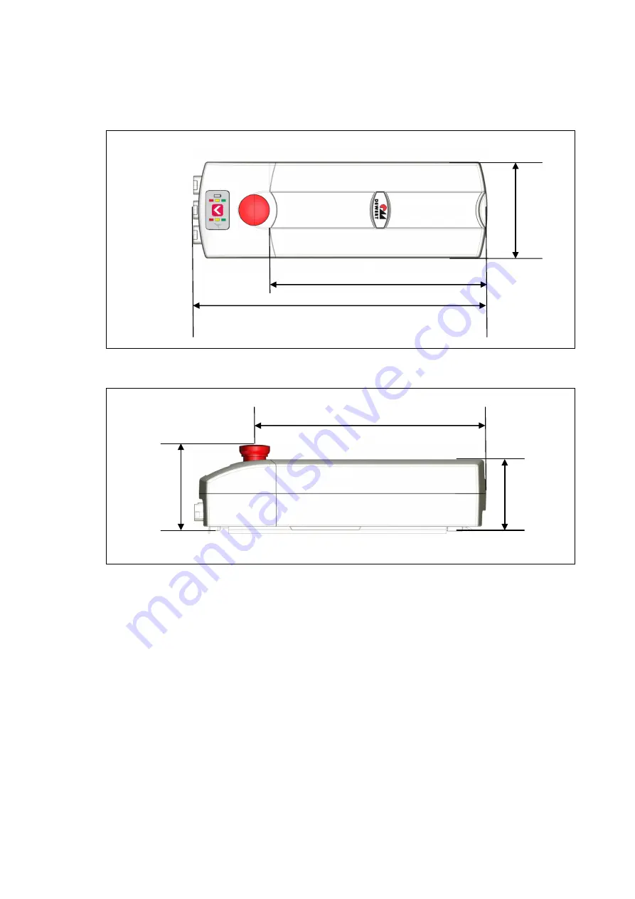
Figure 6
Dimensions of the ACCUCONTROL, top view (in mm)
Figure 7
Dimensions of the ACCUCONTROL, side view (in mm)
90
368
120
107
272.7
292
Страница 1: ...Control unit ACCUCONTROL 4 5 ACCUCONTROL 4 5DC Installation Instructions Translation of the original installation instructions...
Страница 2: ......
Страница 3: ...re end product These instructions are only intended to be used by the end product manufacturer They should not be given to the operator of the end product The factual information contained within may...
Страница 4: ...construction of the ACCUCONTROL has been inspected by the German T V S D Product Service Inspection Authority T V S D Product Service also monitors the production of the ACCUCONTROL The official Germa...
Страница 5: ...ormation 7 1 1 Configurations 7 1 2 About these installation instructions 7 1 3 Conventions used 7 2 Safety notices 8 2 1 Proper and intended usage 8 2 2 Selection and qualification of personnel 9 2 3...
Страница 6: ...ging the ACCU AC 4 5 and ACCU AC 4 5DC 32 7 6 Control panel on the CONTROL 40 7 7 Buttons and indicators on the IPROXX handset an example 42 7 8 Emergency stop switch 43 8 Troubleshooting 44 9 Mainten...
Страница 7: ...in these instructions must be followed Following the guidelines during in stallation and connection procedures will help to minimize the risk of accident and injury and damage to the ACCUCONTROL or t...
Страница 8: ...nment where combustible or explosive gases or vapours e g anaes thesiology may be present in the proximity of open fires or other heat sources such as furnaces ovens or di rect sunlight as a power sou...
Страница 9: ...that the end product can be continually op erated in a safe manner These rules must be observed while using the end product and while in stalling the ACCUCONTROL in the end product These rules and saf...
Страница 10: ...ion for the entire device a section for the ACCU and a section for the CONTROL The following illustrations show where the specifications are located on the ratings plate The ratings plate shown is an...
Страница 11: ...tions yyyyy Article number 24V Input voltage 4 5 Ah Electrical charge Prod date Calendar week year Serial No Serial number IP20 54 Protection degree Use in dry rooms only Pb Follow all special disposa...
Страница 12: ...ns zzzzz Article number 24V Input voltage Max 8 50A Current consumption Duty cycle 2 min ON 18 min OFF Intermittent operations 2 minutes 18 minutes Prod date Calendar week year Serial No Serial number...
Страница 13: ...spreader drive connected with a Y cable a charger and a handset Systems can be customized by combining the drive ACCUCONTROL charger and handset DewertOkin has separate system instruction manuals cont...
Страница 14: ...troke motor IPROXX MEGAMAT XSZ spreader motor 3 2 2 ACCUCONTROL 4 5DC with 1 motor ACCUCONTROL 4DC com bined with MEGAMAT P or GIGAMAT stroke motor IPROXX Adapter cable with the PLUG IN CHARGER 3 2 3...
Страница 15: ...Possible combinations 59245 e 15 3 3 IPROXX handset The following illustrations show the IPROXX handsets that can be used in the different models 3 3 1 Models Basic IPROXX IPROXX 2 3 3 2 Professional...
Страница 16: ...with connection ports for drives the IPROXX handset and the PLUG IN CHARGER The MEGAMAT P MEGAMAT MCZ MEGAMAT XSZ and GIGAMAT drives can be connected to the ACCUCONTROL Figure 5 Components for the ACC...
Страница 17: ...charge 17 V DC ACCU AC 4 5DC1 ACCU AC 4 5 Rated voltage 24 V DC Capacity 4 5 Ah Fuse 7 0 A PolySwitch Battery type Lead rechargeable battery Pb Self discharging After approx 6 months Charging time App...
Страница 18: ...nting rail Approx 700 g ACCU Approx 4 1 kg PLUG IN CHARGER PB 4 5 Input voltage 100 V 110 V 230 V 240 V AC 50 60 Hz Charging voltage nominal 24 V DC Charging current Approx 750 mA Discharge current Ap...
Страница 19: ...ACCUCONTROL Technical specifications 59245 e 19 Figure 6 Dimensions of the ACCUCONTROL top view in mm Figure 7 Dimensions of the ACCUCONTROL side view in mm 90 368 120 107 272 7 292...
Страница 20: ...ing pause times for the ACCU must be observed The unit must not be in operation for at least 1 hour before commissioning before removal and before changing the battery 6 1 2 Avoiding electrical faults...
Страница 21: ...for the control unit The ACCUCONTROL can be bolted to the end product by using two suitable bolts in the two mounting points on the mounting rail The ACCUCONTROL should be mounted so that it lies flat...
Страница 22: ...e must be enough available space to mount the unit 1 Mark both mounting points on the patient lifter 2 Attach the mounting rail along with CONTROL to the patient lifter use the corresponding bolts or...
Страница 23: ...ACCUCONTROL Installation 59245 e 23 Figure 10 Inserting the ACCU in the CONTROL A CONTROL B ACCU C Mounting rail D Housing guide tabs C B A D D...
Страница 24: ...Installation ACCUCONTROL 24 59245 e Figure 11 ACCUCONTROL on the patient lifter A ACCUCONTROL B Patient lifter C Drive B A C...
Страница 25: ...Connecting the components When connecting the components Be sure to connect all components the drives handsets etc Make sure that unused slots are sealed with dummy plugs this ensures that the IP54 le...
Страница 26: ...should be connected to the ACCUCONTROL only approved components have been verified to work together Ask your customer representative for more information Emergency stop switch CAUTION The emergency st...
Страница 27: ...ed whenever the voltage of the ACCU has reached the shutdown threshold level This deep discharge monitor protects the rechargeable battery from damages that could result when the discharge warning is...
Страница 28: ...tone signals that this process has been completed b Option 2 On the programmer handset for the over current detection 1 Use your test system to determine the values for the over current shutdown The...
Страница 29: ...ct sunlight If the batteries leak and you contact the leaked fluid wash with plenty of water and seek medi cal attention immediately Only use the ACCU for its originally intended purpose Do not store...
Страница 30: ...U should not be used for at least 1 hour before changing the battery 2 Slide the ACCU on the mounting rail as shown in Figure 13 until it clicks into place The hous ing guide tabs D must enclose the m...
Страница 31: ...tarting position 2 Press the emergency stop button and remove all plugs from the sockets of the CONTROL Figure 14 Releasing the ACCU A patient lifter B ACCU C Mounting rail D Release lever 3 Grasp the...
Страница 32: ...4 5 to charge the ACCU They have been verified to work properly together Note the following information when charging Charge the ACCU completely for at least 10 hours before first use The built in bat...
Страница 33: ...ACCU should not be used for at least 1 hour before it is removed from the mounting rail 2 Remove the ACCU from the mounting rail as described in section 7 4 CAUTION Follow these safety instructions wh...
Страница 34: ...e that the ACCU is in the correct position while charging The ACCU may only be loaded when it is resting on its base as shown in Figure 16 Do not place the ACCU upside down during charging Figure 16 C...
Страница 35: ...G IN CHARGER PB 4 5 as follows LED is flashing green the ACCU is charging LED is steady green the ACCU is fully charged 5 When the LED on the PLUG IN CHARGER PB 4 5 is steady green pull the PLUG IN CH...
Страница 36: ...rail 2 Remove the ACCU from the mounting rail as described in section 7 4 NOTICE Make sure that the ACCU is in the correct position while charging When using the charging station the ACCU may only be...
Страница 37: ...station B ACCU C Mounting rail D Housing guide tabs 3 Slide the ACCU on the charging station as shown in Figure 19 until it clicks into place The housing guide tabs must enclose the mounting rail to e...
Страница 38: ...N CHARGER PB 4 5 as follows LED is flashing green the ACCU is charging LED is steady green the ACCU is fully charged 7 When the LED on the PLUG IN CHARGER PB 4 5 is steady green pull the PLUG IN CHARG...
Страница 39: ...tem with 1 motor 1 Use the adapter cable or the Y cable to connect the PLUG IN CHARGER PB 4 5 to the CONTROL AC 4 5DC as shown in Figure 21 2 Plug the PLUG IN CHARGER PB 4 5 into the outlet The charge...
Страница 40: ...Charge level indicator Charging state of the ACCU Measure Action Green 100 charged Green yellow Approx 75 loaded Yellow Approx 50 loaded Yellow red Almost completely discharged Recharge the battery pr...
Страница 41: ...ical emergency lowering func tion by pressing the emergency lowering but ton Check for proper function of emergency stop switch Visual inspection for housing damage 5 DEWERT battery unit ACCU 4 5 Visu...
Страница 42: ...B Lifting motor button up C Lifting motor button down D Optional Button spread close E Optional Button spread open F Button reset function G Charge level indicator H Service indicator The function LE...
Страница 43: ...OL Operating notes 59245 e 43 7 8 Emergency stop switch The emergency stop switch deactivates all functionality Figure 24 Emergency stop switch for the CONTROL AC 4 5 CONTROL AC 4 5DC A Emergency stop...
Страница 44: ...ddenly not capable of move ment The overheating protection or system protection has been trig gered Remove the overload change or remove the load Allow the system to rest for 20 to 30 minutes with the...
Страница 45: ...r to the Electrical connection section in the Installation Chapter Periodic inspections can be carried out at intervals based on the risk as sessment which you con duct for your end product Look over...
Страница 46: ...age tempera ture The battery should be charged again after this interval At higher storage temperatures the battery should be recharged more frequently This will help to prevent a complete discharge o...
Страница 47: ...es and metal and plastic parts You should observe all corresponding national and regional environmental regulations when disposing of the ACCUCONTROL The disposal of the end product is regulated in Ge...
Страница 48: ...SION vom 31 M rz 2015 zur nderung von Anhang II der Richtlinie 2011 65 EU des Euro p ischen Parlaments und des Rates hinsichtlich der Liste der Stoffe die Beschr nkungen unterliegen COMMISSION DELEGAT...
Страница 49: ...r the models ACCUCONTROL 4 5 BAS ACCUCONTROL 4 5DC BAS ACCUCONTROL 4 5 PRO and ACCUCONTROL 4 5DC PRO with min IPX4 in ac cordance with EN 60601 1 2006 3rd edition and IEC 60601 Medical electrical equi...
Страница 50: ...an emergency stop switch EN 60601 2 52 Section 201 9 6 2 1 Noise level 65dB A refer to EN60601 2 38 EN 60601 2 52 Section 201 11 1 1 Temperatures EN 60601 2 52 Section 201 11 6 5 101 Protection again...
Страница 51: ......
Страница 52: ...DewertOkin GmbH Weststrasse 1 Kirchlengern 32278 Germany Tel 49 5223 979 0 Fax 49 5223 75182 http www dewertokin de Info dewertokin de ID No 59245...