UM EN OPC 7015/OPC 7022
PHOENIX CONTACT
8155_en_00
9
C
OMPONENT REPLACEMENT
Warning:
Make sure that all cable connections are removed and that all supply voltages are
disconnected from the device!
9.1
O
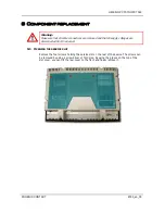
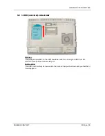
PENING THE SERVICE SLOT
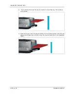
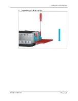
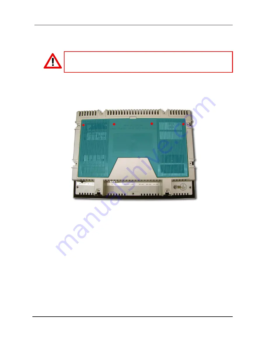
Remove the four screws holding the service slot on the rear of the device. The screws can
be removed by using a screw driver of Tx10 size. By using the groove on the top of the
slot cover, you can tilt the rear cover to the front and finally remove it.
Содержание UM EN OPC 7015
Страница 2: ...UM EN OPC 7015 OPC 7022 8155_en_00 PHOENIX CONTACT...
Страница 15: ...UM EN OPC 7015 OPC 7022 PHOENIX CONTACT 8155_en_00 3 2 EXTERNAL DIMENSIONS OF THE OPC 7013 MODEL...
Страница 16: ...UM EN OPC 7015 OPC 7022 8155_en_00 PHOENIX CONTACT 3 3 INSTALLATION LAYOUT FOR OPC 7013...
Страница 17: ...UM EN OPC 7015 OPC 7022 PHOENIX CONTACT 8155_en_00 3 4 EXTERNAL DIMENSIONS OF THE OPC 7015 MODEL...
Страница 18: ...UM EN OPC 7015 OPC 7022 8155_en_00 PHOENIX CONTACT 3 5 INSTALLATION LAYOUT FOR OPC 7015...
Страница 19: ...UM EN OPC 7015 OPC 7022 PHOENIX CONTACT 8155_en_00 3 6 EXTERNAL DIMENSIONS OF THE OPC 7022 MODEL...


