


TRIO-PS-2G/3AC/24DC/40
105907_en_00
PHOENIX CONTACT
24 / 25
18
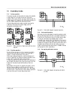
Operating modes
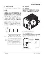
18.1
Series operation
Two power supplies can be switched in series, to double the
output voltage. For connection in series, only power
supplies of the same performance class should be used. An
output voltage of, for example, 48 V DC can be provided, if
two 24 V power supplies are connected in series.
Various voltage levels are made possible by varying the
switching of the respective output voltage and the
measurement reference point.
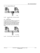
Figure 22
Wiring principle, voltage levels with two power
supplies
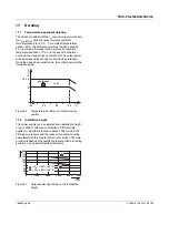
18.2
Parallel operation
Devices of the same type can be connected in parallel to
increase both redundancy and power. By default upon
delivery, no further adjustments are required.
If the output voltage is adjusted, a uniform distribution of
power is guaranteed by setting all parallel operated power
supply units to exactly the same output voltage.
To ensure symmetrical current distribution we recommend
that all cable connections from the power supply unit to the
busbar are the same length and have the same cross
section.
Depending on the system, for parallel connection of more
than two power supplies a protective circuit should be
installed at each individual device output (e.g., decoupling
diode, DC fuse or circuit breaker). This prevents high return
currents in the event of a secondary device fault.
Figure 23
Schematic diagram in parallel operation
18.3
Redundant operation
Redundant circuits are suitable for supplying systems which
place particularly high demands on operational reliability. If
a fault occurs in the primary circuit of the first power supply
unit, the second device automatically takes over the
complete power supply without interruption, and vice versa.
For this purpose, the power supply units to be connected in
parallel must be large enough to ensure that the total current
requirements of all loads can be fully met by one power
supply unit. External decoupling diodes or ORING modules
are required for 100%
redundancy.
18.4
Decoupling with diode module
Figure 24
Schematic diagram, decoupling with diode
module
-48 V
-
+
-
+
+24 V
-24 V
-
+
-
+
+48 V
-
+
-
+
Σ
= I
N
+
–
+ –
-
+
I
N
-
+
I
N
Σ
= I
N
+
–
+ –
-
+
I
N
-
+
I
N


