


TRIO-PS-2G/3AC/24DC/40
105907_en_00
PHOENIX CONTACT
12 / 25
6
High-voltage test (HIPOT)
This protection class I power supply is subject to the Low
Voltage Directive and is factory tested. During the HIPOT
test (high-voltage test), the insulation between the input
circuit and output circuit is tested for the prescribed electric
strength values, for
example. The test voltage in the high-
voltage range is applied at the input and output terminal
blocks of the power supply. The operating voltage used in
normal operation is a lot lower than the test voltage used.
6.1
High-voltage dielectric test (dielectric strength
test) and why must it be performed?
In order to protect the user, power supplies (as electric
components with a direct connection to potentially
hazardous voltages) are subject to more stringent safety
requirements. For this reason, permanent safe electrical
isolation between the hazardous input voltage and the
touch-proof output voltage as safety extra-low voltage
(SELV) must always be ensured.
In order to ensure permanent safe isolation of the AC input
circuit and DC output circuit, high-voltage testing is
performed as part of the safety approval process (type test)
and manufacturing (routine test).
6.2
High-voltage dielectric test during the
manufacturing process
During the manufacturing process for the power supply, a
high-voltage test is performed as part of the dielectric test in
accordance with the specifications of IEC/UL/EN 60950-1.
The high-voltage test is performed with a test voltage of at
least 1.5
kV
AC
/
2.2
kV
DC or higher. Routine
manufacturing tests are inspected regularly by a certification
body.
6.3
High-voltage dielectric test performed by the
customer
Apart from routine and type tests to guarantee electrical
safety, the end user does not have to perform another high-
voltage test on the power supply as an individual
component. According to EN 60204-1 (Safety of machinery
- Electrical equipment of machines) the power supply can be
disconnected during the high-voltage test and only installed
once the high-voltage test has been completed.
6.4
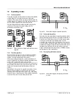
Performing high-voltage testing
If high-voltage testing of the control cabinet or the power
supply as a stand-alone component is planned during final
inspection and testing, the following features must be
observed.
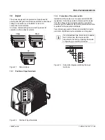
–
The power supply wiring must be implemented as
shown in the wiring diagram.
–
The maximum permissible test voltages must not be
exceeded.
Avoid unnecessary loading or damage to the power supply
due to excessive test voltages.
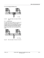
Figure 1
Potential-related wiring for the high-voltage
test
Key
The test voltage should rise and fall in ramp
form. The relevant rise and fall time of the
ramp should be at least seconds.
For the relevant applicable test voltages and
insulation distances, refer to the
corresponding table (see technical data:
electric strength of the insulation section).
No.
Designation
Color coding
Potential
levels
1
AC input circuit
Red
Potential 1
2
High-voltage
tester
--
--
3
Signal contacts
Green (optional) Potential 2
4
DC output circuit Blue
Potential 2
L1
L2
(L3)
Input 2/3 A
C
TRIO PO
WER
DC OK
13
14
+
+
-
-
-
Output DC
4
3
2
1
HV
/=


