23
12V
1 red
+12V
+12V
ground
13 black
Siren +12V
16 pink
Start kill (-)
9 yellow / green
Output to TRUNK
12 greeen
Shock sensor
Additional sensor
Valet
switch
tlačidlo
LE
D
in
di
ca
tio
n
BAT
fuse 10A
output LIGHT
23 brown
input – LIGHT COM
24 brown / black
Connect in depending on light
polartity - positive or negative
output NC1
19 orange
output COM1
17 white
output NO1
18 yellow
output NC2
22 orange/black
output COM2
20 white/black
output NO2
21 yellow/black
UNLOCK
LOCK
fuse 15A
fuse 5A
fu
se
1
5
A
fu
se
1
5
A
Start
ON
OFF
input Door (+)
3 blue
input Door (-)
4 blue / white
output AUX2 (-)
10 grey / white
input Trunk (-)
5 orange / white
input LIGHT CONTROL (+)
6 black / white
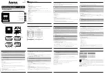
WIRING DIAGRAM of ALARM
ignition (+)
11 orange
ACC
+12V
output AUX1 (-)
8 grey
Security loop
15 black
5 oranž. / biely
MISTRAL MAX
2
PROG
PAGER
output to PAGER (-)
7 green / yellow
Содержание Mistral Max 2
Страница 24: ...24...


