2-3
2-3
Dismantling of the Front Panel assembly
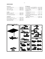
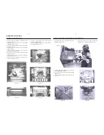
1) Loosen 3 screws D (see Figure 9) to remove the Control
Board (pos 1107-B).
2) Loosen 2 screws E (see Figure 9) to remove the ECO
Standby Board (pos 1107-D).
3) Loosen 4 screws F (see Figure 9) to remove the Volume
Board (pos 1107-H).
4) Loosen 2 screws G (see Figure 9) to remove the Bracket
Combi (pos 252).
5) Loosen 2 screws H (see Figure 10) to remove the
Headphone Board (pos 1107-F).
6) Loosen 6 screws J (see Figure 11) to remove the Display
Board (pos 1107-A).
7) Loosen 4 screws K (see Figure 12) to remove the Shuttle
Board (pos 1107-G).
8) Loosen 2 screws L (see Figure 12) to remove the LCD
Interconnect Board (pos 1107-J).
Dismantling of the Antenna Board, Bracket Antenna and Internet Audio Module
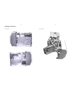
3) Loosen 2 screws N (see Figure 14A) to remove the
Internet Audio Module assembly.
4) Loosen 4 screws P (see Figure 14B) to open the Shield
IAM (pos 262).
5) Loosen 2 screws P1 (see Figure 14C) to remove the Fan
(pos 1111).
Figure 9
Figure 10
Figure 11
Figure 12
Figure 13
9) Loosen 1 screws V (see Figure 12) to remove the Infra
Receiver Board (pos 1107-E).
10) Loosen 2 screws M (see Figure 13) to remove the LCD
Back Light Board (pos 1107-C).
Figure 14A
DISMANTLING INSTRUCTIONS
Figure 14C
Figure 14B
1) Uncatch the catches C5 (see Figure 14) to remove the
Antenna Board (pos 1106).
2) Uncatch the catches C6 (see Figure 14) and push
upward to remove the Bracket Antenna (pos 250).
Figure 14

