Mechanical Instructions
EN 7
SK5.1L CA
4.
4.2.2
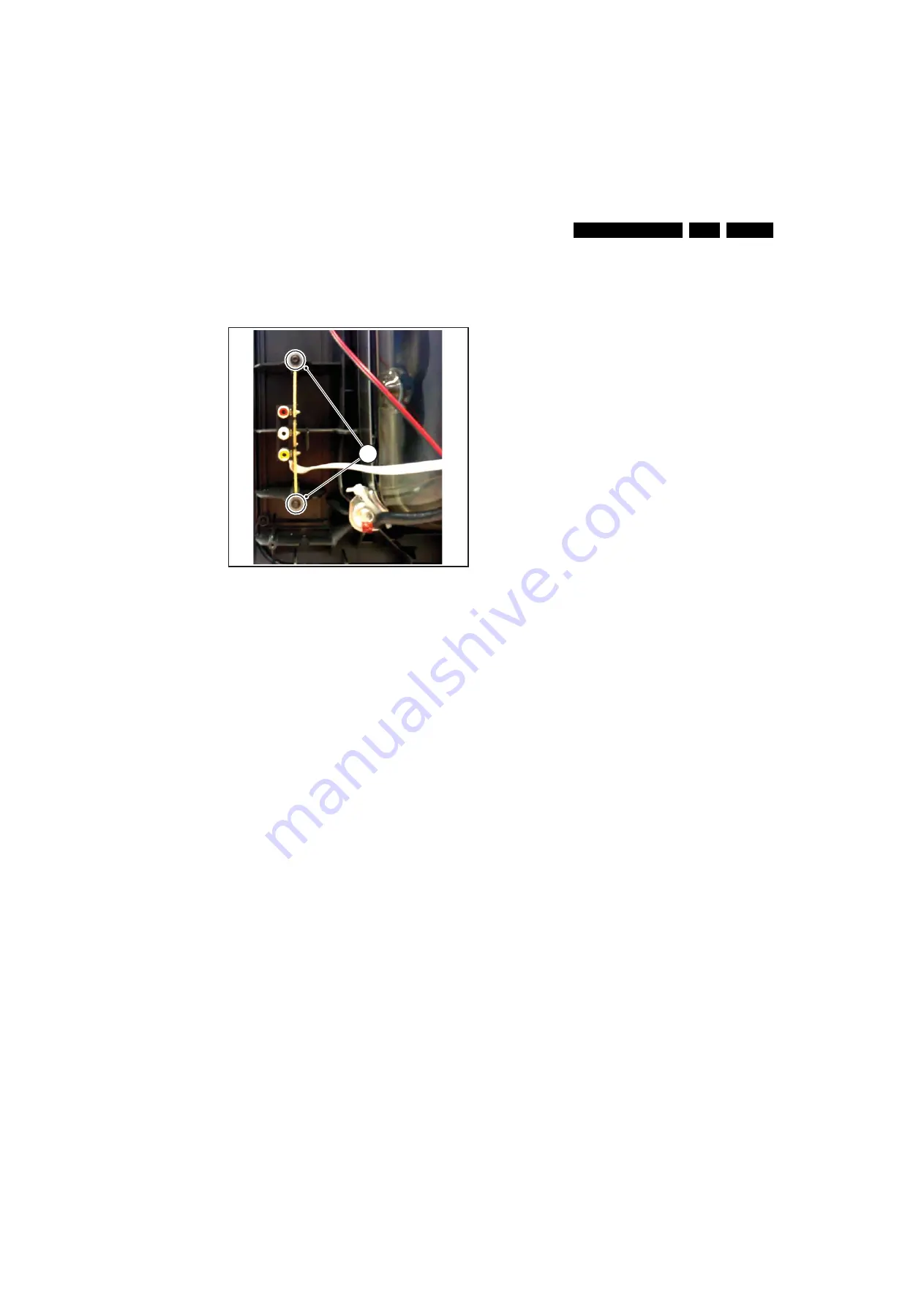
Side I/O Panel removal
Figure 4-3 Side-I/O panel removal
1.
Disconnect the side panel cable from the mono carrier and
remove the cable from it’s strain reliefs.
2.
Then, remove the two fixation screws [1] and remove the
board.
When defective replace the whole unit.
4.3
Set Re-assembly
To re-assemble the whole set, do all processes in reverse
order.
Be sure that, before the rear cover is mounted:
•
The mains cord is positioned correctly in its guiding
brackets (make sure that the strain reliefs are replaced in
its correct position and that it will function correctly!).
•
All wires/cables are returned in their original positions.
I_17
88
0_00
3
.ep
s
270
3
0
8
1
Содержание SK5.1L
Страница 18: ...18 SK5 1L CA 7 Circuit Diagrams and PWB Layouts Layout Mono Carrier Top Side I_17880_018 eps 030408 ...
Страница 19: ...Circuit Diagrams and PWB Layouts 19 SK5 1L CA 7 Layout Mono Carrier Bottom Side I_17880_019 eps 270308 ...
Страница 24: ...24 SK5 1L CA 7 Circuit Diagrams and PWB Layouts Personal Notes E_06532_013 eps 131004 ...
Страница 48: ...Revision List EN 48 SK5 1L CA 11 11 Revision List Manual xxxx xxx xxxx 0 First release ...


