Mechanical Instructions
EN 6
SK5.1L CA
4.
4.
Mechanical Instructions
Index of this chapter:
4.1 Set Disassembly
4.2 Assembly / Board Removal
4.3 Set Re-assembly
Note:
Figures below can deviate slightly from the actual
situation, due to the different set executions.
4.1
Set Disassembly
Follow the disassemble instructions in described order.
4.1.1
Rear Cover Removal
Warning:
disconnect the mains power cord before you remove
the rear cover.
1.
Remove all the fixation screws of the rear cover.
2.
Now, pull the rear cover backwards and remove it.
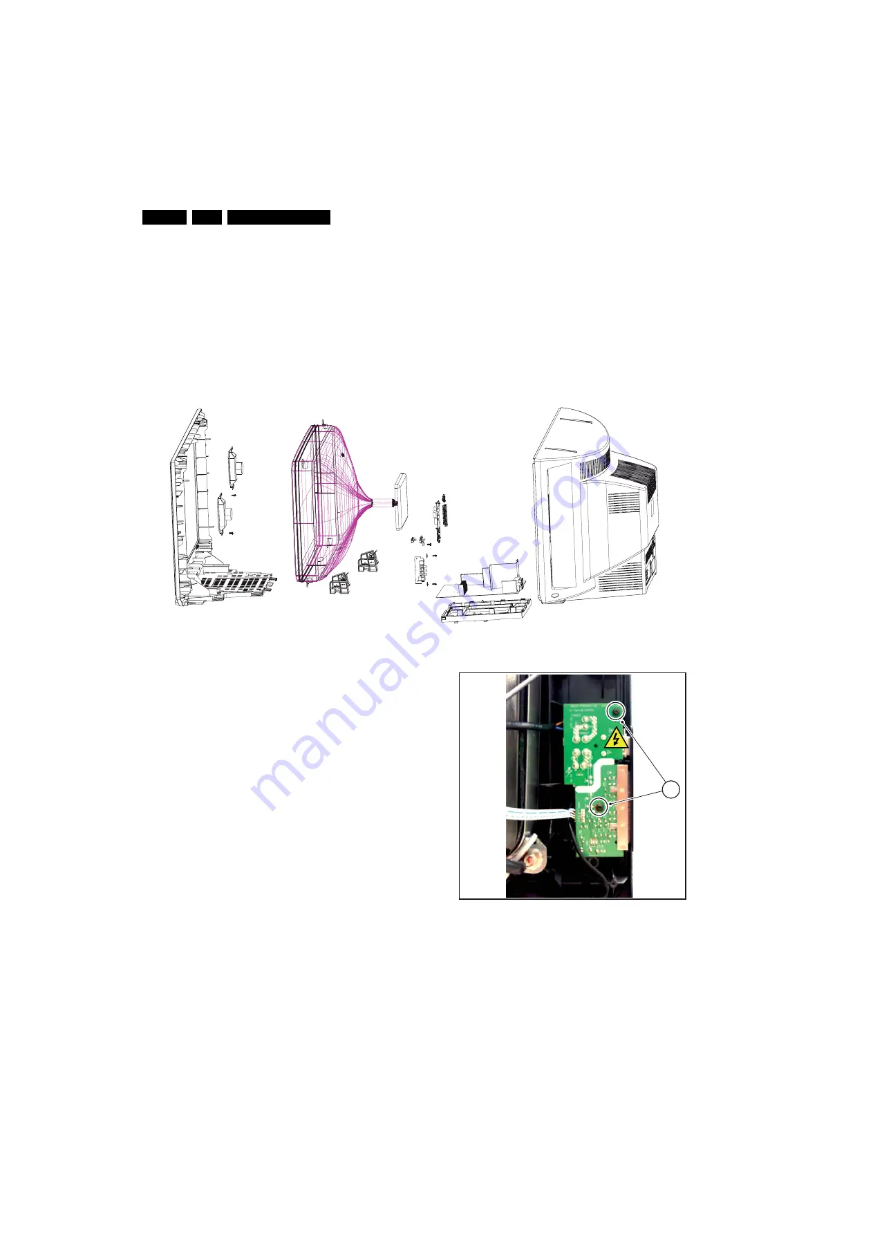
Figure 4-1 Rear Cover removal
4.2
Assembly / Board Removal
4.2.1
Power Switch and Control Panel removal
1.
From the mono carrier disconnect the main power and the
keyboard circuit cables. Release the main power cord and
the keyboard circuit cable from it’s strain reliefs.
2.
Then, remove the two fixation screws [1] of the power
switch and control panel and remove the board.
Figure 4-2 Power Switch and Control Panel removal
I_17
88
0_005.ep
s
210
3
0
8
I_17
88
0_004.ep
s
210
3
0
8
1
Содержание SK5.1L
Страница 18: ...18 SK5 1L CA 7 Circuit Diagrams and PWB Layouts Layout Mono Carrier Top Side I_17880_018 eps 030408 ...
Страница 19: ...Circuit Diagrams and PWB Layouts 19 SK5 1L CA 7 Layout Mono Carrier Bottom Side I_17880_019 eps 270308 ...
Страница 24: ...24 SK5 1L CA 7 Circuit Diagrams and PWB Layouts Personal Notes E_06532_013 eps 131004 ...
Страница 48: ...Revision List EN 48 SK5 1L CA 11 11 Revision List Manual xxxx xxx xxxx 0 First release ...


