background image


EN 20 

9. 

MCP9360i   

Software Update and Repair 


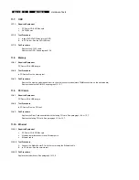
9.5. System 

Recovery 

1. 

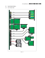
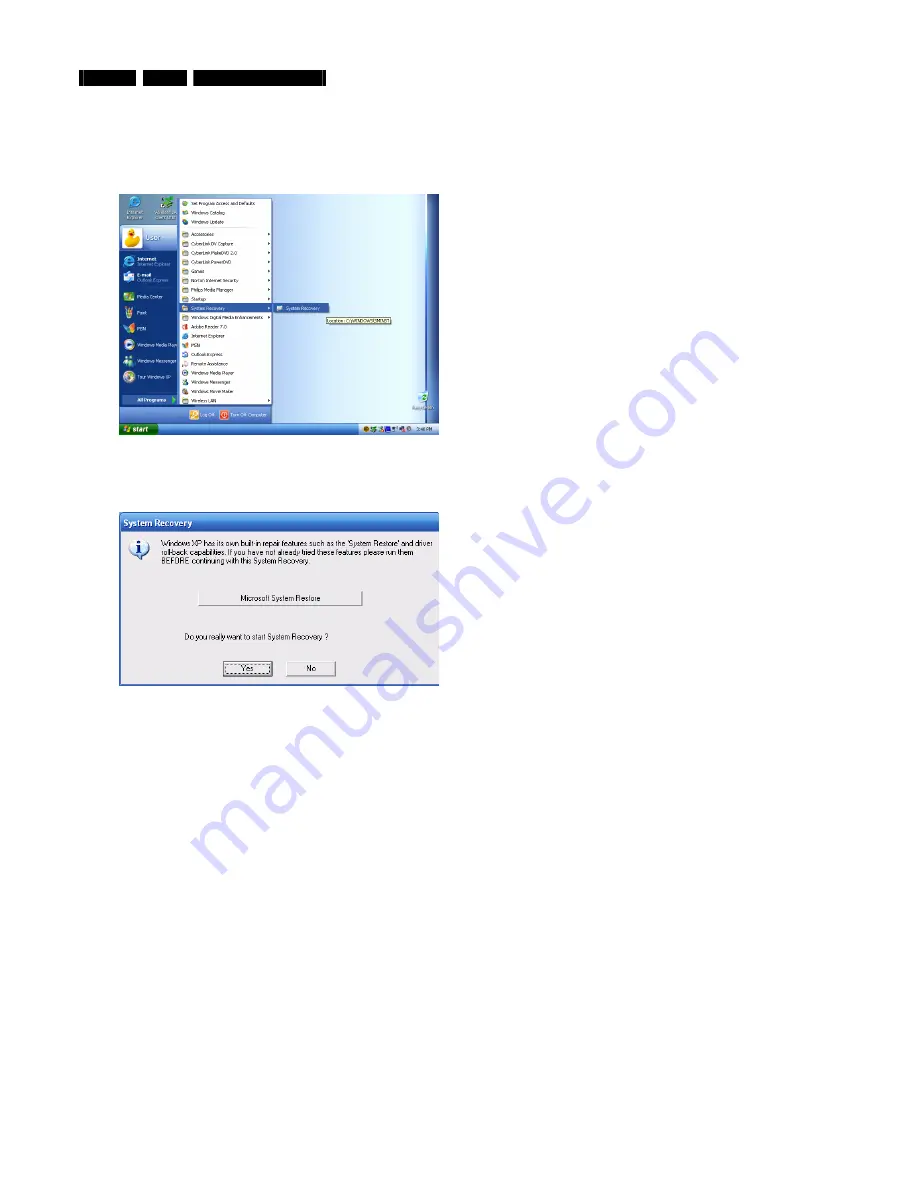
In Windows XP select: 

Start

 > 

All programs

 > 

System Recovery

 > 

System Recovery

. (

Alternatively, press the 

F11

 key during 

boot sequence

). 


Figure 9.5-1 


2. 

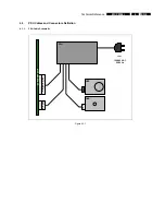
Follow the on-screen instructions to perform a system recovery without performing a format, (operations from this point are carried 
out in DOS mode). 


Figure 9.5-2 


Содержание Showline MCP9360I

Страница 1: ...ir 17 10 PC Doctor Diagnostic Tool 21 11 Hardware Tests 23 12 Hardware Repair 39 13 Software Re installation 62 14 End Test 63 15 Parts Information 64 Copyright 2006 Philips Consumer Electronics B V Eindhoven The Netherlands All rights reserved No part of this publication may be reproduced stored in a retrieval system or transmitted in any form or by any means electronic mechanical photocopying or...

Страница 2: ...fety Information System Overview Basic System Block Diagrams Parts Module Identification Module Functional Descriptions Basic Module Technical Descriptions Basic Measuring Point Information Basic Fault Finding Strategy Module Removal Replacement Procedures Functionality Testing Procedures End Test Sequence Checklist Parts List 12NC Numbers 1 2 Additional Documentation The following documentation i...

Страница 3: ...s are susceptible to electrostatic discharges ESD Careless handling during repair can reduce life drastically When repairing make sure that you are connected with the same potential as the mass of the set via a wrist wrap with resistance Keep components and tools also at this potential 2 3 Notes 2 3 1 Schematic notes All resistor values are in ohms and the value multiplier is often used to indicat...

Страница 4: ...ldering tin parts with leaded soldering tin parts is possible but PHILIPS recommends strongly to avoid mixed regimes If this cannot be avoided carefully clean the solder joint from old tin and re solder with new tin Use only original spare parts listed in the Service Manuals Not listed standard material commodities has to be purchased at external companies Special information for lead free BGA ICs...

Страница 5: ... x 6 pins Philips Media Manager IR blaster 2 x to support up to 3 IR blaster eyes Others TV in Picture Improvement algorithms FM radio in Digital Natural Motion Motion adaptive de interlacing Film mode detector Tuner card AVerMedia TV system PAL SECAM Accessories DVB T DVI to DVI cable DVI to HDMI cable Connection front SCART cable Card reader MS MS pro Memory Stick Digital audio coax cable CF I I...

Страница 6: ...EN 6 4 MCP9360i Technical Reference 4 Technical Reference 4 1 System Block Diagram Figure 4 1 1 ...

Страница 7: ... PCI Riser TV Tuner Card PCI Bus PCI Bus JFP1 JJFP2 VFD Board JUSB1 J2 J9H1 J6A1 J9C2 J7A2 SATA EIDE PCI E Riser ADD2 Board PCI E Bus PCI E Bus SCART Daughter Card Cable 10 SW Board Card Reader JRF1 Cable 4 Cable 5 JFP1 JRF2 Cable 6 RF Board Cable 7 HDD SATA ODD EIDE Cable 8 Cable 9 MOTHERBOARD Front panel Front panel Front panel Rear panel Rear panel Rear panel Figure 4 2 1 ...

Страница 8: ...FP BOARD JFP1 3 FP_USB_CABLE MB J8A2 FP BOARD JFP2 4 VFD_USB_CABLE MB J6A1 VFD Board JUSB1 5 IR_BLASTER_INTERNAL_CABLE MB J9C2 VFD BOARD J2 6 SW_RF_CABLE VFD Board JRF1 SW BOARD JRF2 7 V TYPE_CABLE MB J7A2 1 SW BOARD JFP1 2 CARD READER 8 SATA_HDD_CABLE MB J7F1 HDD 9 ATA33_ODD_CABLE MB EIDE ODD 10 ADD2_SCART_CABLE MB J9H1 1 ADD2 SCART DAUGHTER CARD 2 GRAPHICS CARD ADD2 BOARD ...

Страница 9: ...Technical Reference MCP9360i 4 EN 9 4 3 PSU Cables and Connectors Definition 4 3 1 PSU Cable Schematic HDD ODD 2x12 pin Main 2x2 pin 100 240 VAC 50 60 Hz 4 pin SATA MOTHERBOARD PSU Figure 4 3 1 ...

Страница 10: ...ical Reference 4 3 2 PSU Connector Pin Definition Main Power Connector 2x12 pin Figure 4 3 2 12V Power Connector 2x2 pin Figure 4 3 3 Peripheral Power Connector 4 pin Figure 4 3 4 Serial ATA SATA Power Connector Figure 4 3 5 ...

Страница 11: ... 802 11 b g access point and router with Ethernet LAN ports S video signal source examples DVD player video camcorder Composite video signal source examples DVD player video camcorder RF TV signal source examples external TV antenna cable TV connection VCR RF Radio signal source examples external radio antenna cable connection RF DVB T signal source Cables VGA cable DVI cable SCART cable S Video c...

Страница 12: ...EN 12 6 MCP9360i Diagnosis and Repair Flowchart 6 Diagnosis and Repair Flowchart 9360 Figure 6 1 ...

Страница 13: ...table below System information manufacturer Tatung co Desktop board information manufacturer Intel Corporation Chassis Information Manufacturer Philips MCPC1001 6 Check the BIOS version BIOS menu select Main BIOS version See table below Software module Release version System BIOS SU94510J 86A 0044 2005 0727 0111 7 Check that the HDD and the optical drive have been detected by the BIOS BIOS menu se...

Страница 14: ...riation V 12 0 12 0 V 0 6 V V 5 0 5 0 V 0 25 V V 3 3 3 3 V 0 165 V V 1 5 1 5 V 0 075 V V ccp 1 28 V 0 064 V 11 Exit the BIOS setup screen without saving changes BIOS menu select Exit Exit discarding changes The MCP9360i will now continue to start up Perform the start up sequence check see paragraph 7 3 7 2 2 Fail Procedure Perform Troubleshooting procedure See paragraph 8 ...

Страница 15: ...up sequence for error messages 3 After a short time the Windows Media Center main window or the Windows XP desktop possibly adapted by the user will be shown on screen Figure 7 3 1 Media Center main window English version Figure 7 3 2 Windows XP desktop English version 7 3 2 Fail Procedure Perform Troubleshooting procedure See paragraph 8 ...

Страница 16: ...e PSU cables and measure the voltages See paragraph 4 3 2 If the values are incorrect replace the PSU See paragraph 12 13 1 3 Replace the SW Board See paragraph 12 9 4 Reinsert CPU or replace the CPU See paragraph 12 15 5 5 Replace the motherboard See paragraph 12 15 9 8 3 No Video 1 Make sure that a working monitor is connected and in the correct mode VGA or DVI 2 Remove the memory from the mothe...

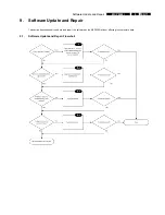
Страница 17: ...te and Repair MCP9360i 9 EN 17 9 Software Update and Repair This section describes how to update and repair the software on the MCP9360i without affecting the customer s data 9 1 Software Update and Repair Flowchart ...

Страница 18: ...tel chipset software installation utility Intel 945G Graphics Intel 82562EZ or 82562EX 10 100 LAN controller Sigmatel Audio Drivers Intel Audio Studio Sonic Focus Lite On Atheros WLAN Tatung Front Panel Manager VFD w button board Tatung VFD Firmware ODD FW AVerMedia TV Tuner LikeMusic CyberLink AP Power DVD Make DVD Capture DV Philips Media Manager Program The latest versions of these applications...

Страница 19: ...pair MCP9360i 9 EN 19 2 Select the restore my system to an earlier time option Figure 9 4 2 3 Select a date in time before the problems were first seen Figure 9 4 3 4 Carefully read the instruction and continue Figure 9 4 4 ...

Страница 20: ...elect Start All programs System Recovery System Recovery Alternatively press the F11 key during boot sequence Figure 9 5 1 2 Follow the on screen instructions to perform a system recovery without performing a format operations from this point are carried out in DOS mode Figure 9 5 2 ...

Страница 21: ...at the dongle is used install the driver for the USB dongle from the PC Doctor disc 4 Start PC Doctor in the Quick Install and Run mode otherwise certain tests will not be enabled See Figure 10 2 1 Figure 10 2 1 5 PC Doctor will now run Select the diagnostics option You are now ready to run one of the tests by selecting one of the icons See Figure 10 2 2 Figure 10 2 2 Note It is recommended that t...

Страница 22: ... cable 5 Insert the USB flash drive containing the batch files 6 In the PC Doctor menu select Test Set Custom Test Settings 7 Open the automated test batch file Automatic PCB from the HDD and start the test sequence 8 Remove the test script from the HDD after the test sequence has finished Interactive tests These tests require some action of the user listening to sound pushing buttons at the keybo...

Страница 23: ...n For swapping swap the cheapest component first e g cables riser boards then the modules and finally the motherboard 2 The cause of the problem is not known Start with the first test see below and continue until one of the tests fails Then swap the failing module etc 3 None of the tests identifies a failing module If the technician suspects that the problem is not covered by the tests he can crea...

Страница 24: ...12 USB controllers Automatic 14 11 13 CMOS Automatic 15 11 14 Motherboard Automatic 16 11 15 IEEE 1394 controller Automatic 17 11 16 Rear Panel Audio Output Connectors Interactive 18 11 17 Wireless keyboard and receiver Interactive 19 11 18 Microphone headphones and headphones volume control Interactive 20 11 19 Wireless network connection Manual 21 11 20 USB connectors Manual 22 11 21 IEEE 1394 c...

Страница 25: ...11 4 3 Fail Procedure Replace the CPU See paragraph 12 15 5 11 5 HDD Hard disk drive 11 5 1 Required Equipment PC Doctor CD USB dongle 11 5 2 Test Procedure In PC Doctor Run the SMART test 11 5 3 Fail Procedure Replace the SATA cable Replace the HDD See paragraph 12 3 Make sure that the latest software image is installed on the replacement HDD See paragraph 13 11 6 Card Reader 11 6 1 Required Equi...

Страница 26: ...IMM connectors on the motherboard Replace the defective DIMM See paragraph 12 15 7 11 9 PCI Cards 11 9 1 Required Equipment PC Doctor CD USB dongle 11 9 2 Test Procedure In PC Doctor Run the PCI test 11 9 3 Fail Procedure Replace the Riser Card associated with the failing PCI card See paragraph 12 6 or 12 7 Replace the failing PCI card See paragraph 12 6 or 12 7 11 10 Ethernet 11 10 1 Required Equ...

Страница 27: ...h 12 6 Replace the ADD2 Graphics card See paragraph 12 6 11 12 USB Controllers 11 12 1 Required Equipment PC Doctor CD USB dongle 11 12 2 Test Procedure In PC Doctor Run the USB test 11 12 3 Fail Procedure Replace the motherboard See paragraph 12 15 9 11 13 CMOS 11 13 1 Required Equipment PC Doctor CD USB dongle 11 13 2 Test Procedure In PC Doctor Run the CMOS test 11 13 3 Fail Procedure Replace t...

Страница 28: ...fier 2 In PC Doctor Run the Sound test 3 Select the first input on the amplifier and push some on screen test buttons to get sound on the different boxes 4 Repeat this for the other three inputs on the amplifier 11 16 3 Fail Procedure Replace the motherboard See paragraph 12 15 9 11 17 Wireless Keyboard and Receiver 11 17 1 Required Equipment PC Doctor CD USB dongle The wireless keyboard that was ...

Страница 29: ...microphone with two 9mm jack plugs 11 18 2 Test Procedure 1 In PC Doctor Run the microphone test and follow the instructions 2 Play the recorded sound a number of times using the volume buttons to increase and decrease the volume 11 18 3 Fail Procedure Replace the FP Audio cable Replace the FP I O board See paragraph 12 11 3 Replace the motherboard See paragraph 12 15 9 ...

Страница 30: ...nection with the wireless access point in the Site Survey section select Refresh and Connect with the access point Make sure that you enter the correct protection key if necessary 3 Select the Status section Both link quality and signal strength should now be sufficiently high Maximum values are 52 0 Mbps and 100 11 19 3 Fail Procedure Replace both antenna cables and antennas See paragraphs 12 8 3...

Страница 31: ...raph 12 15 9 For the rear USB connectors Replace the motherboard See paragraph 12 15 9 11 21 IEEE 1394 Connectors 11 21 1 Required Equipment 1394 device e g external hard disc or a digital camera 4 pin and 6 pin 1394 cables 11 21 2 Test Procedure 1 Insert the 1394 device into one of the 1394 slots 2 Check that the device is detected and that it functions correctly 3 Repeat this procedure for each ...

Страница 32: ...the primary device is digital display and the secondary device is television 5 Switch you monitor and or TV between the different inputs to check if the desktop can be seen on all four Scart DVI VGA and S Video output modes 6 Return the set to the original settings 11 22 3 Fail Procedure For the SCART output Replace the ADD2_SCART cable Replace the SCART connector board See paragraph 12 15 3 Repla...

Страница 33: ...l source examples external FM antenna cable 11 23 2 Test Procedure In MediaCenter select the Radio option and search for a channel 11 23 3 Fail Procedure Replace the PCI riser card See paragraph 12 7 1 Replace the TV tuner card See paragraph 12 7 1 Replace the motherboard See paragraph 12 15 9 ...

Страница 34: ...DVD player camcorder 11 24 2 Test Procedure 1 Connect the Composite Video source to the upper connector on the MCP9360i back panel 2 Connect the TV signal source to the TV RF in connector 3 Go to the TV signal setup section in the Windows Media Center program Select Settings TV Set Up TV Signal 4 Acknowledge that the current settings will be deleted in actuality the procedure will be cancelled at ...

Страница 35: ...N 35 6 Select the manual configuration option this screen is skipped in some versions 7 Select Cable or Digital Cable as the source of the TV signal 8 Select the correct signal type in general NTSC for America PAL SECAM for Europe ...

Страница 36: ...heck if you can see the expected TV signal in the small video window on the right 12 Select Composite Video Check for the expected Composite Video signal in the video window 13 Disconnect the Composite Video cables from the MCP9360i Connect the S Video source to the upper connector on the back panel 14 Select S Video Check for the expected S Video signal in the video window if necessary click Scan...

Страница 37: ...port control buttons located below the VFD display to navigate the CD Check that each button operates correctly 3 Check that the VFD display is functioning 11 25 3 Fail Procedure Replace the VFD_USB cable Replace the VFD board See paragraph 12 12 Replace the motherboard See paragraph 12 15 9 11 26 Remote Control and Infrared Receiver 11 26 1 Required Equipment Use the remote control that was retur...

Страница 38: ...the cables in front of the IR receiver in the front of the set to the left of the VFD display 3 Open a command window Select Start Run Type cmd and click OK 4 In the command window find and run the program IR bat 5 Check if both cables pass the test If not move the eyes a bit and try again until absolutely sure that there is a hardware failure 11 27 3 Fail Procedure Replace the motherboard See par...

Страница 39: ...e 4 torx screws 1 See Figure 12 1 1 2 Slide the top cover towards the rear until the locking tabs disengage See Figure 12 1 2 3 Lift the top cover straight up and remove it from the chassis 4 Store the top cover in a safe place Figure 12 1 1 Figure 12 1 2 1 1 1 1 12 1 2 Top Cover Re Assembly To re assemble the top cover do all steps described in paragraph 12 1 1 in reverse order Note The torque se...

Страница 40: ...il it closes 10 Turn the MCP9360i over so that the topside of the chassis is facing upwards 11 Remove the 2 countersunk screws 3 See Figure 12 2 3 12 Release the main bezel upper locking tab 4 See Figure 12 2 3 13 Pull the top of the main bezel forwards and downwards until the lower locking tabs disengage See Figure 12 2 4 14 Remove the main bezel from the chassis 15 Store the main bezel in a safe...

Страница 41: ...assemble the HDD subassembly do all steps described in 12 3 1 paragraph in reverse order Note The torque setting required for the HDD subassembly mounting screws 2 is 8 kg cm 12 3 3 HDD Removal 1 Remove the HDD subassembly See paragraph 12 3 1 2 Remove the 4 mounting screws and bushes from the HDD 3 Slide the HDD out of the HDD cage 12 3 4 HDD Re Assembly To re assemble the HDD do all steps descri...

Страница 42: ...move the 2 mounting screws 2 from the ODD See Figure 12 4 2 6 Remove the ODD from the chassis by sliding it out towards the front Figure 12 4 1 Figure 12 4 2 2 2 1 12 4 2 ODD Re Assembly To re assemble the ODD do all steps described in paragraph 12 4 1 in reverse order Note The torque setting required for the ODD mounting screws 2 is 4 kg cm Note Before re assembly make sure that the jumper 3 at t...

Страница 43: ...er card See Figure 12 5 2 4 Pull upwards on the riser card bracket 4 until the riser cards are free from the motherboard connectors See Figure 12 5 2 5 Disconnect the SCART cable 5 from the ADD2 Graphics card See Figure 12 5 3 Figure 12 5 1 Figure 12 5 2 3 4 1 1 2 Figure 12 5 3 5 12 5 2 Riser Card Re Assembly To re assemble the riser card subassembly do all steps described in paragraph 12 5 1 in r...

Страница 44: ... PCI E riser card from the riser bracket 8 Push the locking tab arm 5 on the PCI E connector to release the ADD2 Graphics card See Figure 12 6 4 9 Pull the ADD2 Graphics card free from the PCI E riser card connector Figure 12 6 1 Figure 12 6 2 2 2 1 1 1 1 Figure 12 6 3 Figure 12 6 4 3 3 5 4 12 6 2 ADD2 Graphics Card Re Assembly To re assemble the ADD2 Graphics card do all steps described in paragr...

Страница 45: ...uner card and the PCI riser card from the riser bracket 7 Pull the TV tuner card free from the PCI riser card connector Figure 12 7 1 Figure 12 7 2 2 2 1 1 1 1 Figure 12 7 3 3 3 12 7 2 TV Tuner Card Re Assembly To re assemble the TV tuner card do all steps described in paragraph 12 7 1 in reverse order Note Make sure that the TV tuner card is inserted into the correct connector on the PCI riser ca...

Страница 46: ... cover See paragraph 12 1 1 2 Remove the main bezel See paragraph 12 2 1 3 Remove the riser card subassembly See paragraph 12 5 1 4 Remove the ODD See paragraph 12 4 1 5 Remove the CPU heat sink See paragraph 12 14 1 6 Remove the 2 mounting screws 3 from the CPU fan See Figure 12 8 2 7 Remove the 4 mounting screws 4 from the VFD board See Figure 12 8 2 8 Move the CPU fan aside to gain access to th...

Страница 47: ...na Removal 1 Remove the top cover See paragraph 12 1 1 2 Remove the main bezel See paragraph 12 2 1 3 Remove the HDD subassembly See paragraph 12 3 1 4 Remove the ODD See paragraph 12 4 1 5 Remove the riser card subassembly See paragraph 12 5 1 6 Remove the 2 mounting screws 7 from the antenna See Figure 12 8 5 7 Disconnect the left antenna cable from the WLAN card 8 Remove the antenna from the ch...

Страница 48: ...ounting screws 2 from the SW board RF receiver See Figure 12 9 1 5 Remove the SW board RF receiver from the chassis Note The RF receiver may be removed from the SW board by carefully pulling it out of its connector Figure 12 9 1 2 1 2 1 2 2 12 9 2 SW Board RF Receiver Board Re Assembly To re assemble the SW board RF receiver do all steps described in paragraph 12 9 1 in reverse order Note The torq...

Страница 49: ...rd Reader Subassembly Re Assembly To re assemble the card reader subassembly do all steps described in paragraph 12 10 1 in reverse order Note The torque setting required for the card reader subassembly mounting screw 2 is 6 kg cm 12 10 3 Card Reader Board Removal 1 Remove the card reader subassembly See paragraph 12 10 1 2 Remove the 3 mounting screws 3 from the card reader board See Figure 0 3 3...

Страница 50: ...rd See Figure 12 11 1 7 Remove the mounting screw 2 from the FP I O board subassembly See Figure 12 11 2 8 Slide the FP I O board subassembly out from the chassis 9 Disconnect all cables 3 from the rear of the FP I O board See Figure 12 11 3 10 Remove the FP I O board Figure 12 11 1 Figure 12 11 2 2 1 1 Figure 12 11 3 3 12 11 2 FP I O Board Subassembly Re Assembly To re assemble the FP I O board s...

Страница 51: ... mounting screws 4 from the FP I O board See Figure 12 11 4 3 Remove the FP I O board from the FP I O board cage Figure 12 11 4 4 4 4 12 11 4 FP I O Board Re Assembly To re assemble the FP I O board do all steps described in paragraph 12 11 3 in reverse order Note The torque setting required for the FP I O board mounting screws 4 is 6 kg cm ...

Страница 52: ...VFD board See Figure 12 12 3 6 Carefully pull the VFD Board away from the chassis to gain access to the cable connectors 7 Disconnect all cables from the VFD board 8 Remove the VFD board Figure 12 12 1 Figure 12 12 2 1 1 Figure 12 12 3 2 2 2 2 12 12 2 VFD Board Re Assembly To re assemble the VFD board do all steps described in paragraph 12 12 1 in reverse order Note The torque setting required for...

Страница 53: ...he motherboard subassembly See paragraph 12 15 1 8 Remove cable ties 1 from the PSU cables See Figure 12 13 1 9 Remove the mounting screw 2 from the PSU See Figure 12 13 2 10 Slide the PSU towards the front of the chassis to release it from the locking tabs 11 Remove the PSU from the chassis Figure 12 13 1 Figure 12 13 2 1 1 2 12 13 2 PSU Re Assembly To re assemble the PSU do all steps described i...

Страница 54: ...s to gain access to the PSU fan See Figure 12 13 5 9 Remove the 3 mounting screws 5 from the PSU fan See Figure 12 13 6 10 Remove the PSU fan from the chassis Figure 12 13 3 Figure 12 13 4 4 4 3 Figure 12 13 5 Figure 12 13 6 5 5 5 12 13 4 PSU Fan Re Assembly To re assemble the PSU fan do all steps described in paragraph 12 13 3 in reverse order Note The torque setting required for the PSU fan moun...

Страница 55: ...LAN antenna cable 4 from the WLAN card See Figure 12 14 2 10 Move the cables aside to allow access to the CPU heat sink 11 Undo the 4 mounting screws 5 of the CPU heat sink See Figure 12 14 3 12 Remove the CPU heat sink and duct from the motherboard taking care not to catch any cables Figure 12 14 1 Figure 12 14 2 6 7 2 1 3 4 Figure 12 14 3 5 5 5 5 12 14 2 CPU Heat Sink Re Assembly To re assemble ...

Страница 56: ...agraph 12 14 3 in reverse order Note The torque setting required for the CPU fan subassembly mounting screws 8 is 8 kg cm Note Cables must be re assembled into the cable clip in the following order right WLAN antenna cable CPU fan cable IR blaster cable and VFD USB cable Note Fit replacement cable ties after re assembly 12 14 5 CPU Fan Removal 1 Remove the CPU fan subassembly See paragraph 12 14 1...

Страница 57: ... 15 2 12 Disconnect the PSU main power cable 6 from the motherboard See Figure 12 15 2 13 Disconnect the FP audio cable 7 from the motherboard See Figure 12 15 3 14 Disconnect the PSU fan cable 8 from the motherboard See Figure 12 15 3 15 Disconnect the ATA33 cable 9 from the motherboard See Figure 12 15 3 16 Disconnect the SATA cable 10 from the motherboard See Figure 12 15 3 17 Remove the 2 moun...

Страница 58: ... See paragraph 12 15 1 2 Disconnect the ADD2 SCART cable 14 from the motherboard See Figure 12 15 7 3 Disconnect the ADD2 SCART cable 15 from the SCART daughterboard See Figure 12 15 7 4 Remove the 2 mounting screws 16 from the SCART daughterboard See Figure 12 15 7 5 Remove the 2 mounting screws 17 from the SCART connector See Figure 12 15 8 6 Remove the SCART daughterboard from the chassis Figur...

Страница 59: ...Note Apply thermal transfer compound between the CPU and the heat sink 12 15 7 DIMM Replacement 1 Remove the motherboard subassembly See paragraph 12 15 1 2 Release the retaining clips 19 on the DIMM connector See Figure 12 15 10 3 Remove the DIMM from the motherboard Note When a specific DIMM has been identified as faulty by a software test make sure that you can match the identification to the r...

Страница 60: ...teps described in paragraph 12 15 7 in reverse order Note The DIMM connectors must be populated in the correct sequence See figure 12 15 11 for connector identification and population sequence Figure 12 15 11 1st Channel A DIMM 0 3rd Channel A DIMM 1 2nd Channel B DIMM 0 4th Channel B DIMM 1 ...

Страница 61: ...See Figure 12 15 13 8 Remove the 7 mounting screws 22 from the motherboard tray base See Figure 12 15 14 9 Remove the motherboard from the motherboard tray Figure 12 15 12 Figure 12 15 13 20 20 21 21 Figure 12 15 14 22 22 22 22 22 22 22 12 15 10 Motherboard Re Assembly To re assemble the motherboard do all steps described in paragraph 12 15 9 in reverse order Note The torque setting required for t...

Страница 62: ...Insert the DVD with the latest disc image provided by Philips 2 Reboot the MCP9360i 3 Press F for the full recovery option 4 Press Y to continue 5 After 25 minutes the new image will have been installed In some cases it might be possible that the set does not boot from the DVD although this was the default setting In that case 1 Reboot the MCP9360i again 2 During the boot process press F2 to enter...

Страница 63: ...tor See paragraph 10 3 For sets where a software and or hardware repair has been done run the script once The test will take approximately 15 minutes For sets where no repair has been done a check must be made for intermittent faults In PC Doctor make sure that the script is repeated 8 times See Figure 14 1 The test will take approximately 2 hours Figure 14 1 ...

Страница 64: ...ard subassembly 3 1 2 4 6 7 8 12 10 9 6 11 5 16 7 14 3 7 13 18 16 15 17 18 18 19 16 1 Power Supply Unit PSU 12 VFD Board 2 ADD2 Graphics Card 13 Back panel 3 Riser Card subassembly 14 PSU Fan 4 TV Tuner Card 15 SCART Daughterboard 5 Hard Disk Drive HDD subassembly 16 DIMM s 6 Optical Disk Drive ODD 17 CPU 7 CPU Heat Sink 18 WLAN Card 8 CPU Fan subassembly 19 Motherboard 9 SW RF Board 10 Card Reade...

Страница 65: ...Parts Information MCP9360i 15 EN 65 15 2 Cables C3 C2 C1 Figure 15 7 C4 C5 Figure 15 8 C1 IR blaster internal cable C4 V type cable C2 SW RF cable C5 VFD USB cable C3 MD cable RJ11 cable ...

Страница 66: ...G 996500032393 PCI Riser board 996500032392 PCI Express Riser board 996500032395 PAL ADAPTER PAL SPLIP 2 WAY 996500032394 SCART ADAPTER out RCA YC TO SCART 996500032389 FP_1394_CABLE 996500032390 FP_ USB_CABLE 996500032388 FP_AUDIO_CABLE 996500032385 ATA33 ODD CABLE 996500038651 USB WIRELESS KEYBOARD Ne 996500042151 USB WIRELESS KEYBOARD UK 996500042152 USB WIRELESS KEYBOARD SG 996500042153 USB WI...

Страница 67: ... All faulty cables and modules must be stored by the service center for a minimum of two months In that period Philips has the opportunity to ask for shipment to a central location for further analysis After that period the faulty items may be disposed of in an appropriate manner ...

Страница 68: ...EN 68 15 MCP9360i Parts Information NOTES ...

Отзывы: