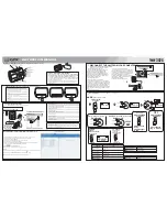
4.0 MECHNICAL INSTRUCTIONS
THE MAIN SET (for PET711 & PET100)
Fig.1
1. Back View as
shown in
Fig.1
Remove screws
on back cabinet
and disconnect the wire on function board
2.
Disc
onnect
wires on
the
DVD
load
er
as
shown in
Fig.2.
3.
Fig.2
Fig.3
Remove screws to
take out
the main PCB
as
shown in
Fig.3.
4.
Fig.4
D
isassembly
the door and function
button discreteness and the middle cabinet
discreteness, remove screws to
take out
the function PCB from the door and function
button discreteness as
shown in
Fig.4.


