3 - 1
CONNECTION AND CONTROLS
IMPOR
T
ANT!
–
The type plate is located at the r
ear of
the system.
–T
he volta
ge selector located at the
rear of this system is pr
eset at
220V
-240V fr
om the factor
y.
F
o
r
countries that operate at 110V
-127V
,
please adjust to 110V
-127V bef
or
e y
o
u
switch on the system.
–
Bef
or
e connecting the
A
C
po
wer cor
d
on the r
ear of the subw
oof
er to the wall
outlet,
ensur
e that all other connections
ha
v
e
been made
.
–N
ev
er mak
e or chang
e an
y
connections with the po
wer s
witched on.
–
High v
oltag
e! Do not open.
Y
ou run the
risk of g
etting an electric shock.
–
The machine does not contain any
user
-ser
viceab
le par
ts.
–
Modification of the pr
oduct could
result in hazar
dous radiation of EMC or
other unsaf
e operation.
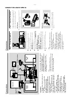
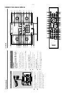
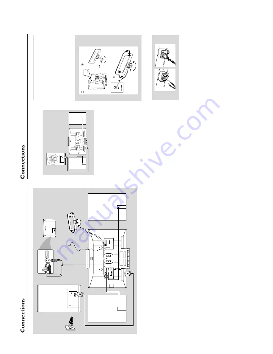
AC CORD
CONNECT
T
O
SUB
WOOFER
R
L
SPEAKERS 6
Ω
Y/Pb/Pr OUT
A/V OUT
AUDIO
IN
S-VIDEO
IN
VIDEO IN
TV IN
AUDIO
IN
S-VIDEO
IN
VIDEO IN
TV IN
AC
p
o
we
r
cor
d
Speak
er
(right)
Speak
er
(left)
FM wir
e antenna
MW loop antenna
To
a
void o
verheating of the system,
a safety
cir
cuit has been built in.
Ther
efor
e
, y
our
system ma
y switch to Standb
y mode
automaticall
y under extr
eme conditions.
If
this ha
ppens,
let the system cool do
wn
bef
ore r
eusing it
(not availab
le f
or all ver
sions).
Note:
–
Bef
or
e installation is f
inished,
it is not
recommended to r
emo
ve the pr
otective plastic f
ilm
attached to the surf
ace of the fr
ont panel to avoid
any scr
atc
h caused during installation.
Subw
oof
er
A/V cor
d
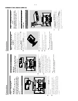
Step 2:
Antennas Connection
Connect the supplied MW loop antenna and FM
antenna to the respectiv
e ter
minals.
Adjust the
position of the antenna f
or optimal reception.
MW Antenna
●
Position the antenna as far as possib
le from a
TV
,
VCR or other r
adiation source
.
FM Antenna
1
2
●
For better FM stereo reception, connect an
outdoor FM antenna to the FM
ANTENNA
ter
minal.
Step 1:
Connecting speak
ers
AC CORD
CONNECT
T
O
SUB
WOOFER
R
L
SPEAKERS 6
Ω
Y/Pb/Pr OUT
A/V OUT
1
Place the main set with the front side facing
down on a flat and f
ir
m
surface
.
2
Connect the tw
o front speak
er cab
les to the
SPEAKERS (6
Ω
)
ter
minals:
r
ight speak
er to
"R" and left speak
er to "L".
3
Remo
ve
the detachab
le co
ver at the left bottom
of the main set to expose the
CONNECT T
O
SUB W
OOFER
ter
minal.
4
Connect the
CONNECT T
O
SUB
W
OOFER
ter
minal of the main set to the
CONNECT
T
O
MAIN SET
ter
minal of the
subw
oofer with the supplied 15-pin D-Sub cab
le
by
matching the pins.
Fix the tw
o screws on the
connector
s to ensure f
ir
m
connection.
5
Mount the detachab
le co
ver back until hearing a
click.
Notes:
–
Ensur
e that the speak
er cables ar
e corr
ectly
connected.
Impr
oper connections may damage the
system due to shor
t-circuit.
–F
or optimal sound perf
ormance
, use the
supplied speak
er
s.
–
Do not connect speak
er
s with an impedance
lo
wer than the speak
ers supplied.
Please r
ef
er to
the SPECIFIC
ATIONS section of this manual.
–
The deliver
y-attac
hed 15-pin D-Sub cable is
intended f
or use with this system only
. Ne
ver tr
y it
on any other de
vices (e
.g.,
do not use it in
connection of your PC).
Содержание MCD299
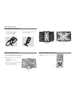
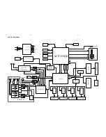
Страница 14: ...WIRING DIAGRAM 5 2 5 2 ...
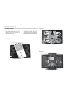
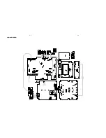
Страница 18: ...LAYOUT DIAGRAM AMP PCB 7 2 7 2 ...
Страница 27: ...LAYOUT DIAGRAM MAIN PCB TOP 8 9 8 9 ...
Страница 28: ...LAYOUT DIAGRAM MAIN PCB BOTTOM 8 10 8 10 ...
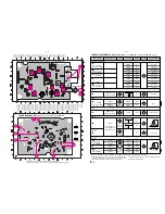
Страница 29: ...LAYOUT DIAGRAM VIDEO PCB USB PCB VGA PCB USB PCB VGA PCB VIDEO PCB 8 11 8 11 ...
Страница 31: ...LAYOUT DIAGRAM DISPLAY PCB 9 2 9 2 ...
Страница 34: ...10 3 10 3 LAYOUT DIAGRAM KEY2 PCB ...

