3 - 2
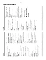
CONNECTION AND CONTROLS
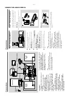
Step 3:
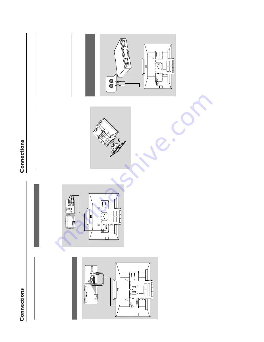
Connecting
TV
IMPOR
T
ANT!
–Y
ou onl
y need to mak
e one video
connection fr
om the follo
wing options,
depending on the ca
pabilities of y
our
TV
.
–
Connect the D
VD system dir
ectl
y to
the TV
.
Using
A
V
OUT jack
AUDIO
IN
S-VIDEO
IN
VIDEO IN
TV IN
AUDIO
IN
S-VIDEO
IN
VIDEO IN
TV IN
CONNECT
T
O
SUB WOOFER
R
L
SPEAKERS 6
Ω
Y/Pb/Pr OUT
A/V OUT
1
Connect the end of the supplied
A
V
cord with
onl
y one connector to the
AV
OUT
jack of the
D
VD system.
2
For the other end, connect the video output
connector (y
ello
w) to the video input jack (or
labeled as
A/
V In,
CVBS,
Composite or
Baseband) on the
TV
. T
o
hear the sound of this
D
VD system through y
our
TV
, connect the audio
connector
s (white/ red) to the audio input jacks
on the
TV
.
Using
Y Pb Pr OUT jack
IMPOR
T
ANT!
–
The pr
o
gressiv
e scan video quality is
onl
y possib
le when using
Y Pb Pr
, and a
pr
o
g
ressiv
e scan
TV is r
equir
ed.
R
CONNECT
T
O
SUB WOOFER
R
L
SPEAKERS 6
Ω
Y/Pb/Pr OUT
A/V OUT
1
Use component video cab
les (red/b
lue/green) to
connect the
COMPOENT VIDEO
OUTPUT
(
Pr/Cr Pb/Cb
Y
) jack to the
cor
responding Component video input jacks (or
labeled as
Y Pb/Cb Pr/Cr or
YUV) on the
TV
.
2
If y
ou are using a Progressiv
e Scan
TV (TV must
indicate Progressiv
e Scan or ProScan capability),
to activate
TV Progressiv
e Scan,
please ref
er to
your
TV user manual.
For D
VD system
Progressiv
e Scan function,
see "Prepar
ations-
Setting up Progressiv
e Scan f
eature".
Note:
–
If your
TV does not suppor
t Pr
ogr
essive Scan,
you
will not be able to vie
w the pictur
e
.
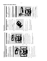
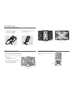
Step 4:
Placing the set and
speak
ers
With the supplied detachab
le stands and wall
mounting kit,
y
ou can either place the main set
and speak
er
s on desktop or mount them onto
wall.
Desktop installation is tak
en f
or example
here
. For ho
w to mount the system onto wall,
please ref
er to
Appendix
and the attached
W
all
Mounting Instructions
.
1
Align the side mar
ked
PRESS
4
of the lar
ger
-
siz
e stand with the slots at the bottom of the
main set.
2
Push the stand do
wn into the slots until y
ou hear
a click.
3
Attach the tw
o smaller
-siz
e stands to the
speak
er
s in the same wa
y.
4
Place the main set and speak
er
s upr
ight on the
desktop with the suppor
t of the stands.
Note:
–T
o r
emo
ve the stand from the main set or either
speak
er
, while pr
essing do
wn PRESS
4
, pull the
stand out fr
om the slots
.
Step 5:
Connecting the po
w
e
r
cor
d
After e
v
er
ything is connected pr
operl
y,
plug in the
A
C
po
w
er cord on the r
ear of
the subw
oof
er to the po
w
er outlet.
Never mak
e or change an
y connection with the
po
w
er switched on.
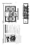
Optional:
Connecting additional
equipment
Listening to the pla
yback of a non-USB
de
vice
A
UDIO OUT
L
R
VCR
(f
or example)
CONNECT
T
O
SUB WOOFER
R
L
SPEAKERS 6
Ω
Y/Pb/Pr OUT
A/V OUT
●
Connect the system's
AU
X IN (R/L)
jacks to
the
A
UDIO OUT
jacks on the other audio/
visual device (such as a
VCR,
Laser Disc pla
yer or
cassette desk)
(cab
le not supplied)
.
●
Bef
ore star
ting oper
ation,
press
SOURCE
on
the front panel to select
AUX or press
AU
X
on
the remote control in order to activate the input
source
.
Содержание MCD299
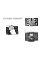
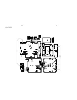
Страница 14: ...WIRING DIAGRAM 5 2 5 2 ...
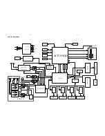
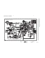
Страница 18: ...LAYOUT DIAGRAM AMP PCB 7 2 7 2 ...
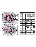
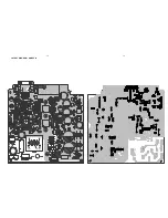
Страница 27: ...LAYOUT DIAGRAM MAIN PCB TOP 8 9 8 9 ...
Страница 28: ...LAYOUT DIAGRAM MAIN PCB BOTTOM 8 10 8 10 ...
Страница 29: ...LAYOUT DIAGRAM VIDEO PCB USB PCB VGA PCB USB PCB VGA PCB VIDEO PCB 8 11 8 11 ...
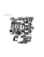
Страница 31: ...LAYOUT DIAGRAM DISPLAY PCB 9 2 9 2 ...
Страница 34: ...10 3 10 3 LAYOUT DIAGRAM KEY2 PCB ...


