CLASS 1
LASER PRODUCT
GB
3140 785 22600
Published by SS 0047 Service Audio
or otherwise without the prior permission of Philips.
system or transmitted, in any form or by any means, electronic, mechanical, photocopying,
All rights reserved. No part of this publication may be reproduced, stored in a retrieval
Copyright 1995 Philips Consumer Electroncis B.V. Eindhoven, The Netherlands
be used.
condition and that parts which are identical with those specified
Safety regulations require that the set be restored to its original
C
PCS 104 676
Printed in The Netherlands
Copyright reserved
Subject to modification
Micro System
TABLE OF CONTENTS
chapter
Handling chip components and safety
1 - 1
MC-55/
21M
.............................
Technical Specification & Service Tools
2 - 1
..........................
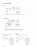
Service Measurement
2 - 2
..................................................
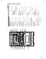
Connections & Controls
3 - 1
................................................
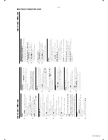
Instructions for use
3 - 2 to 3 - 8
.................................................
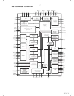
Block Diagram
4 - 1 to 4 - 2
........................................................
Wiring Diagram
5 - 1
...........................................................
circuit diagram
6 - 1
.......................................................
FRONT BOARD
layout diagram
6 - 2
.......................................................
circuit diagram
7 - 1
........................................................
MAIN BOARD
layout diagram
7 - 2
........................................................
circuit diagram
8 - 1
.......................................................
POWER SUPPLY BOARD
layout diagram
8 - 2
.......................................................
chapter
circuit diagram
9 - 1
.......................................................
VCD BOARD
layout diagram
9 - 1
.......................................................
circuit diagram
10 - 1
......................................................
REMOTE CONTROL
layout diagram
10 - 1
......................................................
cabinet
11 - 1
.................................................................
EXPLODED VIEW DIAGRAM
tape deck
11 - 2
.............................................................
Mechanical partslist
11 - 1 to 11 - 2
...............................................
Electrical partslist
12 - 1 to 12 - 3
...............................................
Содержание MC-55
Страница 4: ......
Страница 6: ......
Страница 13: ...PCS 104 686 4 1 BLOCK DIAGRAM IC SAA7324P ...
Страница 14: ...BLOCK DIAGRAM 4 2 PCS 104 687 ...
Страница 15: ...WIRING DIAGRAM 5 1 5 1 PCS 104 688 ...
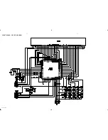
Страница 16: ...FRONT BOARD CIRCUIT DIAGRAM 6 1 6 1 PCS 104 689 ...
Страница 17: ...FRONT BOARD LAYOUT DIAGRAM 6 2 6 2 PCS 104 690 ...
Страница 18: ...MAIN BOARD CIRCUIT DIAGRAM 7 1 7 1 PCS 104 691 ...
Страница 19: ...MAIN BOARD LAYOUT DIAGRAM 7 2 7 2 PCS 104 692 Component Side Copper Side ...
Страница 20: ...POWER SUPPLY BOARD CIRCUIT DIAGRAM 8 1 8 1 PCS 104 693 ...
Страница 21: ...POWER SUPPLY BOARD CIRCUIT DIAGRAM 8 2 8 2 PCS 104 694 ...
Страница 22: ...VCD BOARD CIRCUIT DIAGRAM 9 1 9 1 PCS 104 695 ...
Страница 23: ...VCD BOARD LAYOUT DIAGRAM 9 2 9 2 PCS 104 696 Top View Bottom View ...


