Circuit Descriptions, List of Abbreviations, and IC Data Sheets
EN 63
LC4.2HE AA
9.
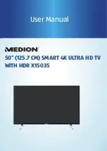
Figure 9-2 Block Diagram LC4.2
The PLL tuner UR1316 (with FM radio) delivers the IF-signal,
via audio & video SAW-filters, to the Video Signal Processor
and FLASH embedded TEXT/Control/Graphics Micro
Controller TDA120x1 (item 7011, also called Hercules). This IC
has the following functions:
•
Analogue Video Processing
•
Sound Demodulation
•
Audio Interfaces and switching
•
Volume and tone control for loudspeakers
•
Reflection and delay for loudspeaker channels
•
Micro Controller
•
Data Capture
•
Display
The Hercules has one input for the internal CVBS signal and a
video switch with 3 external CVBS inputs and a CVBS output.
All CVBS inputs can be used as Y-input for Y/C signals.
However, only 2 Y/C sources can be selected because the
circuit has 2 chroma inputs. It is possible to add an additional
CVBS(Y)/C input (CVBS/YX and CX) when the YUV interface
and the RGB/YPRPB input are not needed. Two SCART-
connectors are used: SCART1 is fully equipped and SCART2
is meant for VCR. Pin 10 of SCART2 is used for Easylink (P50)
and there is a possibility for Y/C in. The CVBS-out on pin 19
can be used for WYSIWYR (What You See Is What You
Record).
The video part delivers the RGB signals to the Scaler IC.
The Genesis GM1501 Malibu Scaler IC can receive two video
input signals: SDTV (from Hercules), DVI (from external DVI
source), or PC (from external computer).
After the video processing, the digital data is sent via a Low
Voltage Differential Signalling bus to the LCD panel. LVDS is
used to improve data speed and to reduce EMI significantly.
There are two I2C lines and two interrupt and communication
lines (TV_IRQ and TV_SC_COM) for the Scaler control. The
Scaler communicates with the Hercules as a slave device. To
avoid buffer overflow at the Scaler side, the TV_SC_COM line
provides the necessary hardware flow control. To allow bi-
directional communication, the Scaler can initiate a service
interrupt-request to the Hercules via the TV_IRQ line.
The Hercules and EEPROM are supplied with 3.3 V, which is
also present during STANDBY.
The EEPROM, or NVM (Non Volatile Memory) is used to store
the settings.
The sound part is built up around the Hercules. The Source
Selection, Decoding and Processing are all done by the
Hercules.
Power supply input are several DC voltages coming from a
supply panel.
9.3
Power Supply
For Service, this supply panel is a black box. When defect (this
can be traced via the fault-finding tips, or by strange
phenomena), a new panel must be ordered (see table below for
ordering codes), and after receipt, the defective panel must be
sent for repair.
Table 9-1 Ordering Codes Power Supply
9.4
Input/Output
The I/O is divided over two parts: Rear I/O and Side I/O. The
rear has two SCART inputs, a PC (VGA) input, a DVI input, and
an Audio input. The side has an audio output for an external
loudspeaker and connectors for an external smartcard
decoding unit.
EXT1
: The input of SCART1 is CVBS + RGB + L/R and the
output is the video (+ sound) signal from the tuner
(SC1_CVBS_RF_OUT).
HERCULE
S
(VDP +
S
TEREO)
TDA9178
CTI/LTI/H
is
t
.
NVM
T
u
ner
TV/FM
3
DYC
u
PCxxx
(Opt
i
on)
LIP
S
YNC
GM1501
(
S
CALER)
NVM
FLA
S
H
S
DRAM
DI
S
PLAY
PANEL
HDMI
Pro
c
e
ss
or
S
peaker
s
& HP
DMMI
(M
u
lt
i
-med
i
a
Interfa
c
e)
Her
cu
le
s
-
Compa
i
r
(
S
erv
ic
e)
VGA
INPUT
HM
L
i
nk
(RJ12)
PC
A
u
d
i
o
INPUT
C
i
n
c
h-to-VGA
Adapter
(YPbPr- HD)
MUX
MUX
ANALOGUE TV
S
CALER
A
u
d
i
o
Amp
E
mbedded
Fl
as
h
I
2
S
YUV
I
n
t
er
f
a
c
e
Ana
lo
g
u
e
I
n
put
24-
bi
t
I
n
put
DVI
I
n
put
DVI-to-HDMI
Adapter
I
2
C
R
GBHV/
YP
b
P
r
R
GB
& HV
Po
w
er
Su
pply Un
i
t
A
C
Mains
I
n
put
HDMI
INPUT
DVI-D
INPUT
Opt
i
o
n:
Choo
se
o
ne
A
V1
A
V2
Side
Co
ns
t
A
u
di
o
Out
TV/IO
s
(
S
CART/C
i
n
c
h)
Compa
i
r
(UART)
DMMI
LVD
S
E
_
144
9
0
_
058
.e
p
s
1
9
0804
Screen size (inches)
Ordering Code
23
3122 137 23070
26
3122 137 23080
Содержание LC4.2HE
Страница 18: ...Service Modes Error Codes and Fault Finding EN 18 LC4 2HE AA 5 Personal Notes E_06532_012 eps 131004 ...
Страница 58: ...58 LC4 2HE AA 7 Circuit Diagrams and PWB Layouts Personal Notes ...
Страница 78: ...Revision List EN 78 LC4 2HE AA 11 11 Revision List Manual xxxx xxx xxxx 0 First release ...