Philips HDD082 Скачать руководство пользователя страница 21

VDDSHVREG

VSS

VDDSHV

C

12

11

10

9

8

7

6

5

4

3

2

1

0

SEL
IN
RST
TICOFF
INH-PG

PG

1
2

TMS
TRST
TDI
TDO
TCK

0

A

CS

DMA

NC

CLK

EMU

D

1

RD
WR
RDY
CS16

ACK

0
1
2

RESET

0

1

DASP

PDIAG

INTRQ

RQ

CF-PF

15

14

13

FB

IN

EN

NC

HS_GND

GND

OUT

NR

NC

NC

NC

NC

NC

NC

NC

GPIO-C

GPIO-E

GPIO-7
GPIO-8

NC

NC

NC

1

NRZD

SE-PINFLIP

CLOCK

SSM-ERR

DATA

SG

RG-WG

NRZDC

7

6

5

4

3

2

0

NC

1

F459 B5

F460 C5

L

J

F442 E12

F443 F12

F444 G13

F445 F11

F446 F11

F447 F11

F448 F11

F449 F11

F450 F11

F451 F11

F452 F11

F453 F11

F454 F11

F455 F11

3

15

G

5

9

8

7

2

12

F456 G11

F457 G11

F458 G11

1

H

3441 E4

3442 D5

3443 E4

3444 C3

3484 B3

3485 F3

3487 C4

3488 C4

3489 C8

3490 B5

4404 D9

5401 E12

7403-1 H9

8

4

gedeeltelijk, is niet toegestaan dan met schriftelijke

N

M

Alle rechten voorbehouden. Verveelvuldiging, geheel of

13

C

5

14

F493 H5

F440 B2

F441 E6

19

P

3

2487 G5

2488 E13

2489 G12

2490 G3

2491 D5

2492 D10

3438 A6

3439 B3

3440 C5

toestemming van de auteursrechthebbende.

E

P

K

7

20

F

E

D

is prohibited without the written consent of the copyright

2455 I12

2458 I13

2460 I13

2462 I13

2463 I14

2464 D3

2465 D5

2466 D10

2467 D9

2468 E3

2469 B2

17

9

D

7403-2 A7

7403-3 F6

7403-4 H6

7403-5 H4

7405 D5

7406 D4

7408 C11

7409 C4

7416 C2

19

14

A

B

C

D

E

F

G

H

I

A

B

C

D

L

13

B

owner.

11

12

10

All rights reserved. Reproduction in whole or in parts

16

11

12

13

14

1

2

3

4

5

6

7

8

9

10

11

2

A

14

12

13

G

H

I

1410 E13

1418 E4

2137 I13

2139 G12

2140 G12

2411 E12

2448 E4

2449 D11

2450 E12

2453 I12

2454 I12

6

O

6

C

A

F

4

9

10

15

G

J

M

10

20

I

1

I

18

K

E

16

B

17

11

F

18

N

O

H

1

2

3

4

5

6

7

8

6.3V

220u

2139

F451

100n

2464

3490

100K

12M

3488

1418

100K

10K

3438

5401

2448

2492

100p

18p

6.3V

220u

2140

F441

F454
F455

F444

100K

3484

F456

F442

10K

3444

100n

2465

33R

M10

L1
K2

B9

3442

F12

C8

N13

A10

A8

B10

B1

J1

K1
J2

A6

G12

H12

E12

D12

C12

H2
H1

A1

A9

B4

B5

B6
B7

F13

G13

A2

A3

A4

A5

B13

G1
G2

C1

F3

A7

H13

B8

E13

J13

B3

Φ

HOST

CF-PF="0"

REVERSE

CONTROL

JTAG

CLOCK & 

TIC-001829-01

7403-2

D13
C13

2

2004-06-11

KONINKLIJKE PHILIPS ELECTRONICS N.V. 2004

2005-04-12

RAYMOND CHOI

2005-04-12

2

3

1

1

1

1

2005-03-24

2005-03-07

2004-12-10

2004-09-23

2004-12-10

A2

PBAS HDD084

HDD084

3140 178 0012

CHECK

DATE

NAME

1

SUPERS.

1

CLASS_NO

CHN

SETNAME

HDD

4

3PC330

2487

F452

130

J4

J10

100n

D8

D5

K4
K8
K9

D6
D9

E10

F4

F10

H4

A11
D7
E4
G4
H10
K5
K6

G3
K7
G10

7403-1

TIC-001829-01

Φ

SUPPLY

1K0

3443

100n

2454

100n

2455

F449

F448

4404

2466

10n

F447

1M0

3441

F446

A12
B11

B2

L2
M2

M9

C7

M8

F460

E2
E1
F1
L12
L13
K12
K13

J12

B12
A13

TIC-001829-01

7403-4

C2
D2
D1

18p

2468

Φ

GPIO

TEST

4

9

8

2
6
7

3

1

Φ

TPS73633DRBR

7408

5

2490

2491

5p6

5p6

BC857B

7409

2460

3485

33R

100n

2467

1u0

100n

2488

100n

2463

F458

100n

2458

2489

100n

4

F445

F440

7416

1

2

3

5

M13

F11

N3
N4

M1

74AHC1G32GW

N1
N2

N5
N6
N7
N8
N9

N10
N11
N12

7403-3

TIC-001829-01

Φ

SE

NORMAL

SE-PINFLIP="1"

F450

3440

100K

2450

100n

M7

L9

L10

M11
M12

K10

C4

D3
C3

D4

M6
M5

L8

C6

D10
D11

C9

C10

M4
M3

E3

L5
L4
L3
L11
K3
K11
J3
J11

C11
C5

L7
L6

H3
H11
G11
F2
E11

F459

7403-5

TIC-001829-01

DSP

Φ

F443

100n

2469

100n

2462

2411

22u

6.3V

2453

100n

F457

2137

100n

2449

10u

F453

100K

6

7

8

9

21

22

3439

15

16

17

18

19

2

20

3

4

5

1

10

11

12

13

14

F493

20FLH-SM1-TB(LF)(SN)

1410

7405

A

2

GND

3

NC

1

5

VCC

Y

4

3

1

5

4

74LVC1G14GW

74LVC1GU04

7406

2

3489

100K

100K

3487

PWR_ACK

ATA_DMARQ

ATA_IORDY

V3V3_D

ATA_RESET

ATA_INTRQ

V3V3_D

ATA_DMAACK

V3V3_D

MPMC_D_(0:15)

V3V3_D

V3V3_D

V3V3_D

ATA_IOWR

ATA_IORD

MPMC_D_(5)

MPMC_D_(0)

MPMC_D_(9)

MPMC_D_(13)

MPMC_A_(11)

MPMC_D_(2)

MPMC_D_(3)

ATA_CS0

MPMC_D_(15)

MPMC_A_(10)

MPMC_D_(7)

ATA_CS1

MPMC_D_(11)

V3V3_D

MPMC_D_(10)

MPMC_D_(12)

MPMC_D_(14)

MPMC_D_(1)

MPMC_D_(4)

MPMC_D_(6)

MPMC_D_(8)

MPMC_A_(12)

V3V3_D

HD_PWR_N

TIC_CLK

V3V3_HDD

VBAT

SE_CLOCK

SE_DATA

SE_NRZD(1)

SE_NRZD(2)

SE_NRZD(3)

SE_NRZD(4)

SE_NRZD(5)

SE_NRZD(6)

SE_NRZDC

SE_RG-WG

SE_SG

SE_SSM-ERR

V3V3_D

SE_NRZD(7)

SE_NRZD(0)

SE_NRZD(1)

SE_NRZD(2)

SE_NRZD(3)

SE_NRZD(4)

SE_NRZD(5)

SE_NRZD(6)

SE_NRZD(7)

SE_NRZDC

SE_SSM-ERR

SE_CLOCK

SE_DATA

SE_RG-WG

SE_SG

SE_NRZD(0)

{SE_NRZD(0:7),SE_NRZDC,SE_SG,SE_RG-WG,SE_DATA,SE_CLOCK,SE_SSM-ERR}

TIC_OFF

V3V3_D

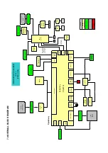
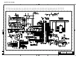
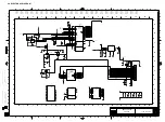
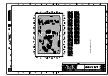
8.0 ELECTRICAL DIAGRAM

Содержание HDD082

Страница 1: ...de testing 6 Overall Block diagram 7 Overall Electrical diagram 8 Component layout 9 Revision list 10 Service Manual Copyright 2005 Philips Consumer Electronics B V Eindhoven The Netherlands All rights reserved No part of this publication may by reproduced stored in a retrieval system or transmitted in any form or by any means electronics mechanical photocopying or otherwise without the prior perm...

Страница 2: ...m support for latest upgrades available Firmware upgrade procedure 1 Download the latest version of the Device Manager application from http www philips com support You may need to enter your language preference and the model number e g hdd084 to access the Device Manager application upgrade file 2 Double click the downloaded execution file to start the installation of the Device Manager 3 Once th...

Страница 3: ...ly removed from the system click OK and unplug your micro jukebox 8 Once the GoGear micro jukebox is disconnected from the computer the display will show Firmware Upgrading for a couple of seconds and then start up as usual If the message does not disappear after 2 minutes do a soft reset by pressing and holding the key and the volume key for a couple of seconds ...

Страница 4: ... caso di non osservazione della più grande cauzione alla loro manipolazione Durante le riparazioni occorre quindi essere collegato allo stesso potenziale che quello della massa dell apparecchio tramite un braccialetto a resistenza Assicurarsi che i componenti e anche gli utensili con quali si lavora siano anche a questo potenziale Pour votre sécurité ces documents doivent être utilisés par des spé...

Страница 5: ...IEW To switch between root menu library and now playing screens 7 3 4 Scroll SuperScroll 3 4 J Rewind Fast forward Up Down to 1 level Skip to previous next y 2 Power on off and Play Pause confirms a menu setting 8 Neckstrap eyelet 9 Volume Volume control 0 REC Start or Stop Voice recording PLAYLIST Add the current track to My Playlist MIC Microphone hdd084_ENG qxd 6 16 05 4 37 PM Page 3 3 0 Instru...

Страница 6: ...ICAL INTRUCTIONS Set Disassembly 1 Remove the Cosmetic screw with an Allen key 2 Use a screwdriver to carefully lift up the back cover of the device 3 Gently open up the back cover 4 Remove 4 x screws See arrows ...

Страница 7: ...tom part 6 Remove the battery pack and then the hard disk 7 Take out the 2 screws on the PCB assembly to replace the board from the casing Overview of the disassembly parts Hard Disk Mainboard LCD module Bottom parts Battery Back cover Top assembly Key set ...

Страница 8: ...121 314017900181 PCBA KIT ASSY HDD084 17 PCBA KIT ASSY HDD082 17 107 314017800131 PCBA KIT ASSY HDD084 97 108 282206200083 310420052301 HDD 1 0 3GB 000936 02 CORN Y HDD 1 2GB HDD082 17 109 314017400331 DAMPER HDD084 110 314017750321 KEYSET FRONT ASSY HDD084 111 314017750181 LENS PRI ASSY HDD084 112 314017040031 SCREW HEXAGON HDD084 MISCELLENEOUS 908210004736 Headphone SHE775BI 00 314017310091 Neck...

Страница 9: ...Key Test LCD Backlight Test 5 key Remote Key Test SDRAM Read Write Test SDRAM Self refresh Test HDD Test Audio Test FM Tuner Test Battery Level Test Battery Charging Test MIC Recording Test Real Time Clock Test EEPROM Test UP LEFT LEFT LEFT LEFT 5 Key Remote Test LEFT Programming the device using for stand alone FSM The following is the description for programming the device in stand alone mode 1 ...

Страница 10: ...selected by pressing RIGHT key will be as shown below 20 Write to RTC Note scroll bar to indicate the test selected can be used provided the UI FSM DVT FW does not exceed 1 MB 1 1 3 LCD Back Light Test LCD Backlight Device Key 5 key Remote Key LCD Remote Key Steps Scroll to LCD Test using UP Down Key Press RIGHT to enter the test LCD Test is displayed on the LCD Press RIGHT to see the first bitmap...

Страница 11: ...ESTING The Test patterns which will be displayed will be as shown LCD pattern 1 White screen LCD pattern 3 Checkerboard pattern LCD pattern 2 Black screen with a white square at right upper corner LCD pattern 4 Black background ...

Страница 12: ...keys are pressed the test is exited after a brief delay and the test browse screen will be entered where next test can be selected Steps NOTE THAT LEFT KEY PRESSES CAN EXIT THIS TEST Scroll to Device KEYPAD Test using UP Down Key Once all keys are pressed the test success screen is displayed Press RIGHT to enter the test Keypad Test is displayed on the LCD The result is as shown Press all keys one...

Страница 13: ...D HDD084 SDRAM Self Refresh Test SDRAM Under Test HDD084 SDRAM Self Refresh Test SDRAM Self refresh FAIL This test can be exited in between the testing process by pressing LEFT key Verification of SDRAM Read Write Functionality To Verify SDRAM Read Write Functionality Write a pattern 0x55aa55aa to a specific location and read back the data to verify the data Integrity HDD084 SDRAM R W Test SDRAM U...

Страница 14: ... auto search mode This test can be exited in between the testing process by pressing LEFT key Whenever a station is found the frequency and Signal strength are displayed on the LCD Press PLAY PAUSE Key to set Stereo Mode TBC Verification of HDD Functionality Press PLAY PAUSE key to set Mono Mode TBC FM recording Test can be performed along with the tuner test as mentioned in 4 1 14 After connectin...

Страница 15: ...XXV YYY YmA CHG STATUS Adaptor STATUS Note this test should be done without initialising the HDD HDD084 BATTERY LEVEL TEST X XXXV CAL STATUS USB CHARGING MODE Battery Charging Test Steps If the USB connection is made the system will startup in the low power mode trickle charging 100mA include system current and after the enumeration process SW can decide whether high power mode can be switched on ...

Страница 16: ...Test using UP Down Key Press RIGHT to enter the test If the test is successful RTC TEST OK is shown on LCD if the Test fails RTC TEST FAIL is shown on the LCD Press LEFT to exit the test Verification of RTC When user selected the RTC test Software will write a pre defined register value to the RTC FM Recording Test After 1 second Software will read back the RTC register value and check if the RTC ...

Страница 17: ...e test If the test is successful EEPROM TEST OK is shown on LCD if the test fails EEPROM TEST FAIL is shown on the LCD Press LEFT to exit the test Appendix I Verification of EEPROM Functionality Firmware Upgrade To Verify EEPROM Functionality Write a pattern 0x55aa55aa to a specific location and read back the data to verify the data Integrity repeat the write read test by pattern 0xaa55aa55 Steps ...

Страница 18: ...6 0 FACTORY SERVICE MODE TESTING HDD initialisation Steps Select the test and press right key to enter the test Initialize the HDD ...

Страница 19: ...CM 96x64 B W LNA MIC amplifier Line In 12MHz sysclock Line Out Headphone Out 32KHz RTCclock I2C interface EEPROM M24C08 RTC FM tuner Headphone connector UART Constant Current Source VBacklight JTAG MultiICE connector mode selection switches Reset logic Reset Analog Keys on the Device USB_SUSPEND USB_HIGH_PWR PWR_ACK CHG_STATUS BATT_LOW_N LEGEND BOARD COMPONENTS CONNECTORS EXTERNAL DEVICES HDD084 O...

Страница 20: ...07 10R 1402 SKRE 2n2 2401 3301 8R2 F417 F486 56K 100R 3429 F489 3482 1 2 3 4 5 6 7 8 9 TCX0101 110177 1406 3450 100R 3496 10K 22K 1 100n 3460 2429 330p 2307 2484 100n 4401 1 10K 3462 BAT54C 6103 F436 1414 100n SKQY 2438 3428 10K 6 3V 220u 2300 OSCI 2 OSCO 6 SCL SDA 5 8 VDD VSS 4 7401 PCF8563TS 7 CLKO 3 INT_ 1 2476 1u0 470K 1 10K 3402 3494 100n 2436 2404 2412 100n 22p F423 5 3 4 7412 2 BC847BS 3433...

Страница 21: ...ROL JTAG CLOCK TIC 001829 01 7403 2 D13 C13 2 2004 06 11 KONINKLIJKE PHILIPS ELECTRONICS N V 2004 2005 04 12 RAYMOND CHOI 2005 04 12 2 3 1 1 1 1 2005 03 24 2005 03 07 2004 12 10 2004 09 23 2004 12 10 A2 PBAS HDD084 HDD084 3140 178 0012 CHECK DATE NAME 1 SUPERS 1 CLASS_NO CHN SETNAME HDD 4 3PC330 2487 F452 130 J4 J10 100n D8 D5 K4 K8 K9 D6 D9 E10 F4 F10 H4 A11 D7 E4 G4 H10 K5 K6 G3 K7 G10 7403 1 TI...

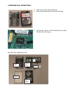
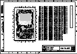
Страница 22: ...9 0 COMPONENT LAYOUT ...

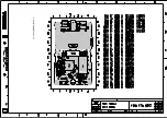
Страница 23: ...9 0 COMPONENT LAYOUT ...

Страница 24: ...9 0 COMPONENT LAYOUT ...

Страница 25: ...Q ASSY HDD084 SIL 314017750172 o REAR CABINET ASSY HDD084 314017750132 Chapter 5 Adding of the following new service parts o HDD 1 2GB SW CONFIG HDD082 17 314017050361 o USB CABLE ASSY 314011769601 Version 1 3 3141 785 30483 Chapter 5 New PCBA kits with different resistor value are used o PCBA KIT ASSY HDD084 00 314017900191 o PCBA KIT ASSY HDD084 05 314017900111 o PCBA KIT ASSY HDD084 17 31401783...

Отзывы: