background image

GC7430

5-8

TRAY RUBBER CAP 30

TRAY ASSY 33

DOOR ASSY

Remove  

TRAY RUBBER CAP 30 (3x)

Remove 

Screw F1, F2, F3

Disassemble 

TRAY ASSY 33

Remove 

Screw G

Disassemble 

DOOR ASSY

FRONT PANEL PRINTED 37

POWER BOARD 43

CONTROL BOARD

Remove  

TRAY RUBBER CAP 30 (3x)

Remove 

Screw F1, F2, F3

Disassemble 

TRAY ASSY 33

Remove  

Screw H1, H2

Disassemble 

FRONT PANEL 37

Remove 

Screw J1, J2

Disassemble 

PCB BRACKET

Disassemble 

CONTROL BOARD

Disassemble 

POWER BOARD 43

DISASSEMBLY ADVICE - STAND

WATER TANK ASSY 34

HOSE CORD CAP 36

BOILER ASSY 38

BRAIDED RUBBER HOSE - 

BOILER

PUMP ASSY 45

INLET TUBE - PUMP

DE-AIR TUBE

RINSE RUBBER COUPLING 50

RINSE BUSH

RINSE CAP ASSY 52

Remove  

TRAY RUBBER CAP 30 (3x)

Remove 

Screw F1, F2, F3

Disassemble 

TRAY ASSY 33

Remove  

Screw H1, H2

Disassemble 

FRONT PANEL 37

Disassemble 

HOSE CORD CAP 36

Disassemble 

RINSE CAP ASSY 52

Disassemble 

RINSE BUSH

Disassemble 

RINSE RUBBER COUPLING 50

Remove 

Screws K1, K2, K3, K4

Disconnect 

INLET TUBE - PUMP

Disconnect 

DE-AIR TUBE

Disassemble  

WATER TANK ASSY 34

Disassemble  

BRAIDED RUBBER HOSE - BOILER

Disassemble  

PUMP ASSY 45

Remove 

Torx screws L1, L2, L3

Disassemble 

TOP SPACER

Disassemble 

BOILER ASSY 38

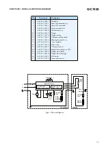
PARTS LIST - STAND

Note:  For Pos 45, please replace both components together when either one is faulty. 

The 2 components come as a service kit.

Pos

Service code

Description

30
33
34
36
37

38
40
42
43
45

4239 015 58701
4239 021 55751
4239 021 55711
4239 026 38361
4239 021 55691

4239 021 39540
4239 017 09890
4239 010 10260
4239 021 40360

4239 022 63002

Tray rubber cap
Tray B assy
Water tank assy
Hose cord cap
Front panel C printed assy

Boiler assy - High End
Electrovalve
Inox clamp
Power board
Control board-Pump assy kit

Pos

Service code

Description

50
52
55
56
58

65

4239 015 56760
4239 021 55671
4239 000 10080
4239 021 55661
4239 026 05990

4239 026 42081

Rinse rubber coupling
Rinse cap assy
Cord set EU
Stand bottom B assy
Filling cup

De-air valve

= changed

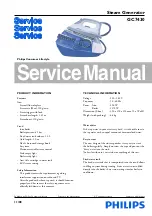
Содержание GC7430

Страница 1: ...nd TV After the product has been repaired it should function properly and has to meet the safety requirements as officially laid down as this moment TECHNICAL INFORMATION Voltage 220 240 V Frequency 50 60 Hz Power Iron 800 W Boiler 1370 W Dimension F box 350 x 350 x 250 mm L x W x H Weight with packing 6 4 kg Water advice If the tap water in your area is very hard it is advisable to mix the tap wa...

Страница 2: ... rear HOUSING Part 2 DISASSEMBLY ADVICE IRON INLAY 4 LAMP ASSY 7 MICROSWITCH ASSY 9 TRIGGER 12 THERMOSTAT DIAL ASSY 14 HOUSING PRINTED 16 SOLEPLATE COVER 17 THERMOSTAT BUSH 19 RUBBER HOSE BRASS JOINT SOLEPLATE ASSY 23 Remove Screw A Disassemble BACKPLATE 1 Disassemble TRIGGER 12 Tip Disassemble TRIGGER by inserting a sharp object into the gap at the rear of the trigger prying upward Remove Screw C...

Страница 3: ...19 23 24 25 26 27 4239 026 38261 4239 021 55931 4239 021 55651 4239 021 46071 4239 021 42390 4239 026 38221 4239 014 54370 4239 021 55641 4239 021 55621 4239 026 38181 4239 015 70150 4239 026 13220 4239 021 41330 4239 015 56120 4239 015 56510 4239 026 38241 4239 021 31780 Backplate Hose cord mounted assy Inlay SOS soft touch Lamp mounted assy Microswitch assy Trigger Trigger spring Thermostat dial...

Страница 4: ...GC7430 4 8 EXPLODED VIEW IRON A 7 Cord clamp E1 D1 D3 D2 C B1 B2 E2 E3 2 17 18 1 14 12 13 4 26 9 25 19 16 27 24 23 ...

Страница 5: ...isassemble RINSE RUBBER COUPLING 50 Remove Screws K1 K2 K3 K4 Disconnect INLET TUBE PUMP Disconnect DE AIR TUBE Disassemble WATER TANK ASSY 34 Disassemble BRAIDED RUBBER HOSE BOILER Disassemble PUMP ASSY 45 Remove Torx screws L1 L2 L3 Disassemble TOP SPACER Disassemble BOILER ASSY 38 PARTS LIST STAND Note For Pos 45 please replace both components together when either one is faulty The 2 components...

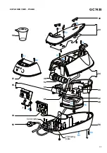
Страница 6: ...GC7430 6 8 EXPLODED VIEW STAND 58 F1 K1 H1 H2 K2 K4 K3 F2 G F3 40 56 38 42 34 36 52 50 55 Cord clamp Clamping plate 37 43 L2 L3 L1 J1 J2 45 65 30 33 ...

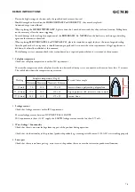
Страница 7: ... Soleplate temperature Check that soleplate temperature is within IEC requirement Measure the temperature of the soleplate after the iron has reached steady state i e connected to the mains for at least 15 minutes The table below shows the temperature requirement Marking Soleplate temperature Deg C Material for example Test point Minimum Maximum Nominal Tolerance 1 dot 70 120 95 25 Acetate elastan...

Страница 8: ...GC7430 8 8 REPAIR INSTRUCTIONS Pump Assy Wire connections Connector positions in DOTTED circle cannot be interchanged Single wire connector BLACK BLACK A LIGHT GREY Dual wire connector ...

Отзывы: