GC7430
3-8
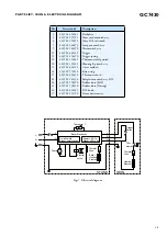
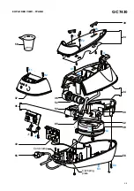
PARTS LIST - IRON & ELECTRICAL DIAGRAM
STAND
IRON
L
N
Boiler Electronics
On/off switch
Steam select switch
Power LED 1x
Steam LED's 3x
Thermal
Fuse
Thermal
Fuse
Pump
Thermistor 1
L
N
L
S
N
M
Boiler
Heating
Element
Electro-
valve
Ther-
mostat
Trigger
Switch
Heating
Element
Fig 4 . Electrical diagram
Pos
Service code
Description
1
2
4
7
9
12
13
14
16
17
18
19
23
24
25
26
27
4239 026 38261
4239 021 55931
4239 021 55651
4239 021 46071
4239 021 42390
4239 026 38221
4239 014 54370
4239 021 55641
4239 021 55621
4239 026 38181
4239 015 70150
4239 026 13220
4239 021 41330
4239 015 56120
4239 015 56510
4239 026 38241
4239 021 31780
Backplate
Hose cord mounted assy
Inlay SOS soft touch
Lamp mounted assy
Microswitch assy
Trigger
Trigger spring
Thermostat dial printed
Housing B printed assy
Cover molded
Ryton ring
Thermostat bush
Soleplate mounted assy SOS
Rubber hose (SOS)
Rubber hose (Dosing)
SOS knob
Steam deviator assy

