


Circuit Descriptions and Abbreviation List
EN 108
9.
A basic fly-back converter is used, with a MOSFET Q1,
transformer L1, and a primary feedback circuit. The output of
the primary controlled voltage is U1.
The additional secondary controlled supply consists of D2 and
Q2, with output voltage U2.
The main fly-back supply is working independently, where the
duty cycle is controlled via the primary feedback, and the
MOSFET Q1 is switching at a certain frequency. MOSFET Q2
is also switching at the same frequency, as it is synchronised
with Q1.
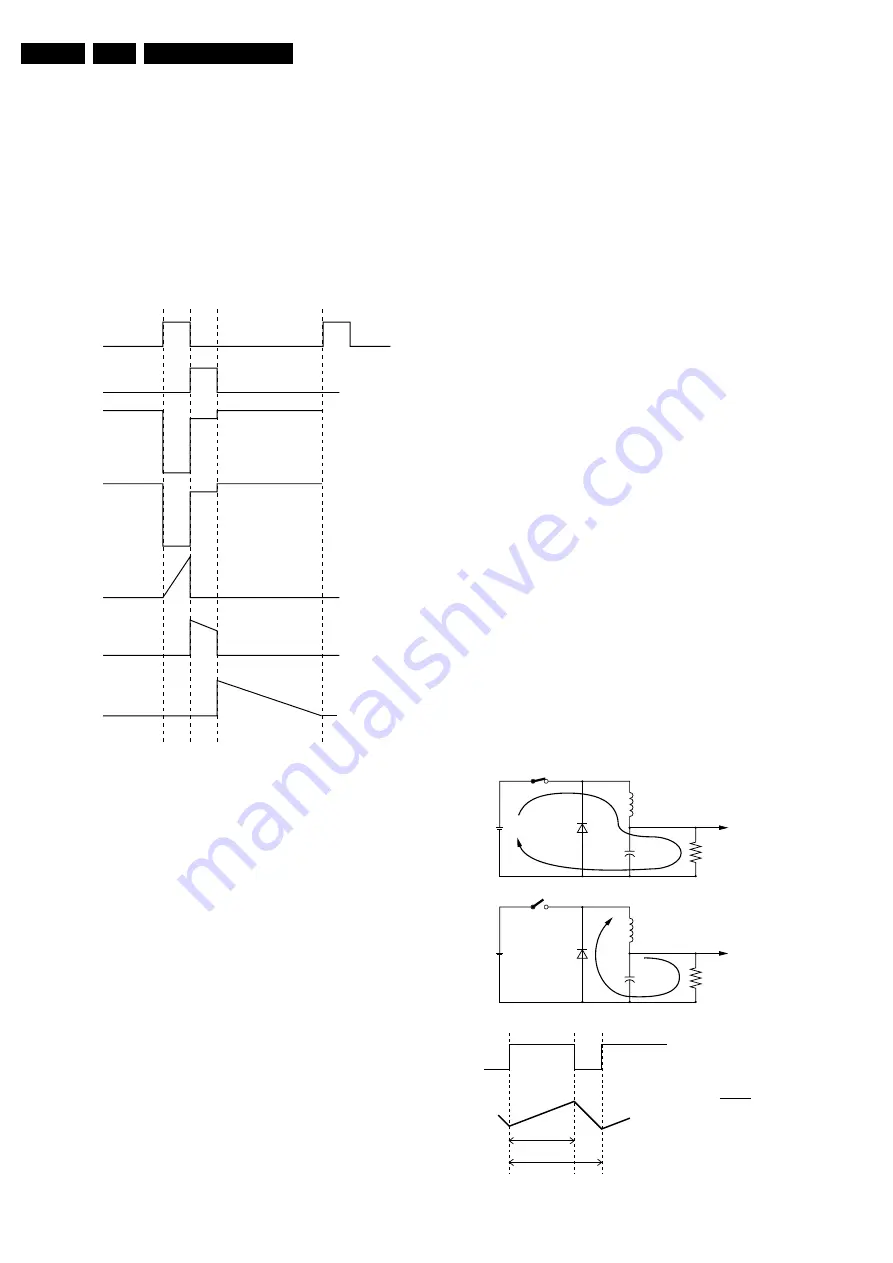
Figure 9-7 Timing diagram
•
Time interval t0-t1: The primary MOSFET Q1 is switched
'on', both diodes D1 and D2 are blocked.
•
Time interval t1-t2: MOSFET Q1 is switched 'off' and Q2
is switched 'on'. During this period, the energy is
transferred to output U2 of the supply. Diode D1 is blocked,
because U3 is lower than U1.
•
Time t2: Q2 is switched 'off'.
•
Time interval t2-t3: During this period, the rest of the
energy will be transferred to output U1.
The two controllers, the primary feedback for U1, and the
secondary feedback for U2, all work independently.
The secondary voltage U2 is controlled by the 'on' time of Q2.
As soon as the load on U2 increases, the 'on' time of Q2 (the
period t1-t2) is automatically increased by the secondary
feedback. More energy will be taken by the output U2, and less
energy will be transferred to U1. Automatically U1 will drop.
The primary feedback loop will change the primary drive to
enlarge the total amount of energy to be transferred, from the
primary side, and U1 will rise again.
Protection
If the optocoupler would fail, the secondary voltage will
increase. This would have disastrous consequences since
many ICs (e.g. OTC, Flash-RAM and DRAM) are fed with this
5.2 V. In other words, very expensive repairs would be
required.
We already know that the negative supply is directly dependent
upon the secondary 5.2 V, because of which the negative
supply will increase proportionally as the secondary voltage
increases.
If the negative supply in the mean time reaches -25 V, D6106
will start to zener and therefore TS7101 will start conducting.
D6106 will take over the stabilisation task of the optocoupler,
however, with a considerable spread: from -20 to -25 V is a 25
% increase, thus U
OUT
will increase from 5.2 V to max. 6.5 V.
Tuner Supply
The Standby supply produces two voltages for the Tuner: +33V
(V
TUN
) and +5VT.
The +33V is the tuning voltage for the Tuner.
The +5VT is derived from the +8V with stabiliser 7912 (see
diagram A8), and is used to supply the tuner only.
SSB Supply
There are several voltages going to the SSB: +8V6, +5V2 and
+3V3.
The +5V2 and +8V6 (always present) come directly from the
Standby power supply.
The +3V3 is derived from the +5V with stabiliser 7910 (diagram
A8).
9.3.4
Main Supply (Diagram A1)
The main power supply is able to deliver a continuous power
between 100 W and 160 W.
Some important notes on beforehand:
•
V
BAT
is not isolated from the main supply ('hot').
•
V
BAT
is alignment free.
Principle
The Main Power Supply, generates the 141 V (V
BAT
) and the +/
- 16 V for the audio part. It is based on the so-called 'down
converter' principle.
Figure 9-8 Down-converter principle
CL 26432041_079.eps
170402
t0
Vg-Q1
Vg-Q2
V-D1
V-D2
I1
I2
I3
t1 t2
t3
96532156_022.eps
060100
R
L
I
T
I
T
V
BAT
Vin
S
C
L
R
L
I
D
I
D
V
BAT
Vin
S
C
L
Sclosed
Sopen
δ
T
V
IN
.
δ
T
T
+
+
D
D
VBAT =
T
Содержание EM5E
Страница 7: ...Directions for Use EN 7 EM5E 3 3 Directions for Use ...
Страница 8: ...Directions for Use EN 8 EM5E 3 ...
Страница 9: ...Directions for Use EN 9 EM5E 3 ...
Страница 10: ...Directions for Use EN 10 EM5E 3 ...
Страница 11: ...Directions for Use EN 11 EM5E 3 ...
Страница 12: ...Directions for Use EN 12 EM5E 3 ...
Страница 13: ...Directions for Use EN 13 EM5E 3 ...
Страница 14: ...Directions for Use EN 14 EM5E 3 ...
Страница 15: ...Directions for Use EN 15 EM5E 3 ...
Страница 16: ...Directions for Use EN 16 EM5E 3 ...
Страница 17: ...Directions for Use EN 17 EM5E 3 ...
Страница 18: ...Directions for Use EN 18 EM5E 3 ...
Страница 19: ...Directions for Use EN 19 EM5E 3 ...
Страница 20: ...Directions for Use EN 20 EM5E 3 ...
Страница 36: ...Service Modes Error Codes and Fault Finding EN 36 EM5E 5 Personal Notes ...