background image

EN 7

3139 785 31510

Measurements Setup, Service Aid & Lead Free Requirements

2.

GB

WARNING

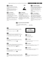
All ICs and many other semi-conductors are
susceptible to electrostatic  discharges (ESD).
Careless handling during repair can reduce life
drastically.
When repairing, make sure that you are
connected with the same potential as the mass
of the set via a wrist wrap with resistance.
Keep components and tools also at this
potential.

F

ATTENTION

Tous les IC et beaucoup d’autres
semi-conducteurs sont sensibles aux
décharges statiques (ESD).
Leur longévité pourrait être considérablement
écourtée par le fait qu’aucune précaution n’est
prise à leur manipulation.
Lors de réparations, s’assurer de bien être relié
au même potentiel que la masse de l’appareil et
enfiler le bracelet serti d’une résistance de
sécurité.
Veiller à ce que les composants ainsi que les
outils que l’on utilise soient également à ce
potentiel.

ESD

D

WARNUNG

Alle ICs und viele andere Halbleiter sind
empfindlich gegenüber elektrostatischen
Entladungen (ESD).
Unsorgfältige Behandlung im Reparaturfall kan
die Lebensdauer drastisch reduzieren.
Veranlassen Sie, dass Sie im Reparaturfall über
ein Pulsarmband mit Widerstand verbunden
sind mit dem gleichen Potential wie die Masse
des Gerätes.
Bauteile und Hilfsmittel auch auf dieses gleiche
Potential halten.

NL

WAARSCHUWING

Alle IC’s en vele andere halfgeleiders zijn
gevoelig voor electrostatische ontladingen (ESD).
Onzorgvuldig behandelen tijdens reparatie kan
de levensduur drastisch doen verminderen.
Zorg ervoor dat u tijdens reparatie via een
polsband met weerstand verbonden bent met
hetzelfde potentiaal als de massa van het
apparaat.
Houd componenten en hulpmiddelen ook op
ditzelfde potentiaal.

I

AVVERTIMENTO

Tutti IC e parecchi semi-conduttori sono
sensibili alle scariche statiche (ESD).
La loro longevità potrebbe essere fortemente
ridatta in caso di non osservazione della più
grande cauzione alla loro manipolazione.
Durante le riparazioni occorre quindi essere
collegato allo stesso potenziale che quello della
massa dell’apparecchio tramite un braccialetto
a resistenza.
Assicurarsi che i componenti e anche gli utensili
con quali si lavora siano anche a questo

potenziale.

GB

ESD PROTECTION EQUIPMENT:

Complete Kit ESD3 (small tablemat, wristband,

connection box, extention cable and earth cable) ........... 4822 310 10671

Wristband tester .................................................................... 4822 344 13999

CLASS  1

LASER PRODUCT

GB

Warning !

Invisible laser radiation when open.
Avoid direct exposure to beam.

S

Varning !

Osynlig laserstrålning när apparaten är öppnad och spärren
är urkopplad.  Betrakta ej strålen.

SF

Varoitus !

Avatussa laitteessa ja suojalukituksen ohitettaessa olet alttiina
näkymättömälle laserisäteilylle. Älä katso säteeseen!

DK

Advarse !

Usynlig laserstråling ved åbning når sikkerhedsafbrydere er
ude af funktion. Undgå udsaettelse for stråling.

F

"Pour votre sécurité, ces documents doivent être utilisés par
des spécialistes agréés, seuls habilités à réparer votre
appareil en panne".

GB

Safety regulations require that the set be restored to its original
condition and that parts which are identical with those specified,
be used
Safety components are marked by the symbol 

!

.

NL

Veiligheidsbepalingen vereisen, dat het apparaat bij reparatie in
zijn oorspronkelijke toestand wordt teruggebracht en dat onderdelen,
identiek aan de gespecificeerde, worden toegepast.
De Veiligheidsonderdelen zijn aangeduid met het symbool 

!

F

Les normes de sécurité exigent que l’appareil soit remis à l’état
d’origine et que soient utiliséés les piéces de rechange identiques
à celles spécifiées.
Less composants de sécurité sont marqués 

!

D

Bei jeder Reparatur sind die geltenden Sicherheitsvorschriften zu
beachten. Der Original zustand des Geräts darf nicht verändert werden;
für Reparaturen sind Original-Ersatzteile zu verwenden.
Sicherheitsbauteile sind durch das Symbol 

!

 markiert.

I

 Le norme di sicurezza esigono che l’apparecchio venga rimesso
nelle condizioni originali e che siano utilizzati i pezzi di ricambio
identici a quelli specificati.
Componenty di sicurezza sono marcati con 

!

GB

After servicing and before returning set to customer perform a leakage
current measurement test from all exposed metal parts to earth ground to
assure no shock hazard exist. The leakage current must not exceed
0.5mA.

Содержание Cineos HTS9800W/55

Страница 1: ...right 2005 Philips Consumer Electronics B V Eindhoven The Netherlands All rights reserved No part of this publication may be reproduced stored in a retrieval system or transmitted in any form or by any means electronic mechanical photocopying or otherwise without the prior permission of Philips Version 1 0 Contents Page Contents Page Interface Board Layout Bottom View 47 Mains Board Schematic 48 M...

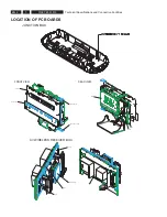
Страница 2: ...ecifications and Connection Facilities LOCATION OF PC BOARDS JUNCTION BOX FRONT VIEW FRONT LED TOP FRONT LED BOTTOM DISPLAY TOUCH PANEL REAR VIEW MPEG TUNER PSU AMPLIFIER AMPLIFIER WIRELESS RECEIVER INTERFACE PSU AV WIRELESS RECEIVER BOX ...

Страница 3: ...S9800W 12 HTS9800W 37 55 Video Yellow Cinch x Component Video Y Pb Pr P scan x x SCART CVBS RGB x Digital In Coaxial x x TV In Left Right x x Auxiliary Left Right x x HDMI x x Power Amp VGA x x WIRELESS TRANSMITTER VGA PSU MAINS SOCKET SPEAKERS CONNECTORS INTERFACE AMPLIFIER AMPLIFIER POWER BOX ...

Страница 4: ...iting point 8µV Crosstalk at RF 1mV dev 67 5kHz 28dB 1 3 AMPLIFIER Total output power 6600W PMPO 550W RMS L R output power 1 x 46W type 50W Centre 1 x 95W type 100W Surround 1 x 46W type 50W Subwoofer 1 x 95W type 100W Frequency response 3dB 150Hz 20kHz Hum Volume Minimum 200nW Residual noise Volume Minimum 40nW Input sensitivity Aux In 1V 3dB at 39kΩ Scart In 1V 3dB at 39kΩ 1 4 COMPACT DISC VCD D...

Страница 5: ...s 250Hz 15kHz e g 7122 707 48001 LF Voltmeter e g PM2534 DUT S N and distortion meter e g Sound Technology ST1700B Frame aerial e g 7122 707 89001 Tuner AM MW LW To avoid atmospheric interference all AM measurements have to be carried out in a Faraday s cage Use a bandpass filter or at least a high pass filter with 250Hz to eliminate hum 50Hz 100Hz RF Generator e g PM5326 Ri 50Ω Bandpass 250Hz 15k...

Страница 6: ...al Torx driver holder 4822 395 91019 Torx bit T10 150mm 4822 395 50456 Torx driver set T6 T20 4822 395 50145 Torx driver T10 extended 4822 395 50423 Compact Disc SBC426 426A Test disc 5 5A 4822 397 30096 SBC442 Audio Burn in Test disc 1kHz 4822 397 30155 SBC429 Audio Signals disc 4822 397 30184 Dolby Pro logic Test Disc 4822 395 10216 ...

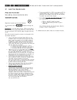
Страница 7: ...la massa dell apparecchio tramite un braccialetto a resistenza Assicurarsi che i componenti e anche gli utensili con quali si lavora siano anche a questo potenziale GB ESD PROTECTION EQUIPMENT Complete Kit ESD3 small tablemat wristband connection box extention cable and earth cable 4822 310 10671 Wristband tester 4822 344 13999 CLASS 1 LASER PRODUCT GB Warning Invisible laser radiation when open A...

Страница 8: ... avoid wear out of tips switch off un used equipment or reduce heat Mix of lead free solder alloy parts with leaded solder alloy parts is possible but PHILIPS recommends strongly to avoid mixed solder alloy types leaded and lead free If one cannot avoid or does not know whether product is lead free clean carefully the solder joint from old solder alloy and re solder with new solder alloy SAC305 Us...

Страница 9: ...ut a paper clip on the flexfoil to short circuit the contacts fig 1 5 Replace the defective loader with a new loader 6 Remove paperclip from the flexfoil and connect it to the new loader 7 Remove solder joint on the ESD protection point ATTENTION The laser diode of this loader is protected against ESD by a solder joint which shortcircuits the laserdiode to ground For proper functionality of the loade...

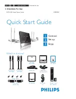
Страница 10: ... system AV subwoofer Remote Control and 2 batteries h s i l g n E DVD SACD HOME THEATER SYSTEM HTS9800W User Manual User manual Junction Box AV Wireless Receiver Box DVD SACD Home Theater System HTS9800W VGA cable use this cable to connect the Junction Box to AV subwoofer Speaker cables Power cable x 2 2006 01 16 5 04 10 PM 3 Directions for use 3 Directions For Use ...

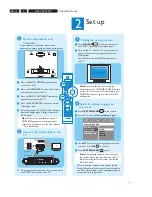
Страница 11: ... receiver box is not placed in an enclosed area B Base view of the speaker stand Both the coloured stickers must match A C Placement and Connections A Assemble the speakers A Connect the speaker stand with the supplied speaker wire Match the colour of the speaker wire to the colour of the socket on the base of the speaker stand Hold down the socket tab while inserting the stripped portion of the s...

Страница 12: ...the display language on the screen A Press SYSTEM MENU on the remote B Press É to select General Setup Page C Use keys to select a language option in the menu and press OK to confirm D Press SYSTEM MENU to exit Note The language selected here is only for the system menus that are shown on the TV while operating this DVD system not for the DVD disc menu There are various system setup options Audio ...

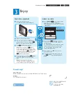
Страница 13: ...C Once complete use keys to select a preset radio station D To delete a preset radio station press and hold STOP until PRESET DELETED appears AUTO INSTALL D A Insert a disc into the disc slot Make sure the disc label is facing out EJECT B Playback will start automatically C If the disc menu appears use keys to select an option in the menu and press PLAY on the remote to start playback D Press STOP...

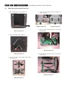
Страница 14: ... screws to remove Shield Figure 4 6 4 1 Dismantling of the Main Unit 1 Remove Cover and loosen 7 screws as shown in Figure 4 1 Figure 4 1 2 Loose 4 screws to remove the Bracket Pos 131 Figure 4 2 3 Loosen 4 screws to remove Display Board Figure 4 3 4 Dismantling Instructions 4 3 3 6 4 Dismantling Instructions Service Positions 1 1 2 5 5 ...

Страница 15: ... 7 Dismantling Instructions Service Positions 4 GND POINT A GND POINT B 4 2 Dismantling of the Wireless Box Surround 1 Loosen 4 screws to remove the Cover for the Wireless Box Surround Figure 4 11 2 Loose 4 screws each to remove the Amplifier Board Figure 4 12 3 Loose 4 screws to remove the Wireless Receiver Figure 4 13 4 Loosen 4 screws to remove the PSU Module Figure 4 14 1 1 2 2 GND POINT B GND ...

Страница 16: ...igure 3 and pull the Power Box Assy Subwoofer Figure 4 17 4 Dismantling Instructions Service Positions A B B C C 4 Loosen 2 screws as shown in Figure 4 Figure 5 to remove the shield Subwoofer Figure 4 18 Subwoofer Figure 4 19 5 Loosen 4 screws as shown in Figure 6 to remove the Interface Board Subwoofer Figure 4 20 6 Loosen 8 screws as shown in Figure 7 to remove the Amplifier Board Subwoofer Figur...

Страница 17: ...tructions Service Positions 4 4 4 Dismantling of the Junction Box 1 Loosen 2 screws Junction Box Europe Figure 4 22 Junction Box AP Figure 4 23 2 Loosen 2 screws Junction Box Figure 4 24 3 Loosen 4 screws Junction Box Figure 4 25 G G H I ...

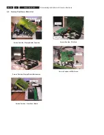
Страница 18: ...ce Position Display Board Topview Service Position Display Board Bottomview Service Position Front Panel Board Service Position PSU Unit Service Position MPEG Board Display Board Top Insulation Sheet Display Board Bottom Front Panel Insulation Sheet PSU module Insulation Sheet MPEG Board Insulation Sheet ...

Страница 19: ...x Service Position Subwoofer Service Position Amplifier Interface Board Service Position PSU Module 4 6 Service Positions Junction Box Subwoofer unit Wireless Box Surround Junction Box Insulation Sheet Insulation Sheet Interface Board Amplifier Board Interface Board Amplifier Board Insulation Sheet ...

Страница 20: ...o check for open circuits Pattern 2 Alternate display control pins are ON Test Pattern 0x55 Mode Dim 2 is selected Brightness is 25 to check for short circuits TEST Activated with ACTION EEPROM FORMAT TEST to Exit Load default data Display shows NEW Caution All presets from the customer will be lost S refers to Service Mode V refers to Version xx refers to Software version number of BEA counting u...

Страница 21: ...ISO9660 is mandatory UDF discs are not supported The final CDROM must not contain any other data except the file from the zip archive 5 1 4 Procedure to upgrade the firmware 1 Power up the set and open tray 2 Insert the prepared Upgrade CDROM and close the tray 3 The set will display 1 LOAD after read the disc the tray is ejected out 2 ERASE Erasing Disc 3 WRITE Writing Disc 4 ERROR if unsuccessful 5...

Страница 22: ...EN 22 3139 785 31510 5 Service Test Program Notes ...

Страница 23: ...4HC4052 TM 10 1n0 POWER AMP L R SAA6581T M62429FP GND 11 12 13 14 8 7 6 5 20 19 18 17 16 15 F G H I F E D C 3 4 5 6 7 8 9 10 15 16 17 18 19 20 14 13 K 4 3 2 1 J L M N O P P O A B C D E N M L K J I H G B A 1 2 12 11 10 9 3139_249_3297_Block_Diagram_Pg1 pdf_030806 6 Block Diagram Block Diagram Wiring Diagram ...

Страница 24: ... 6 7 8 9 10 11 12 A B C D F G H I J J 2 3 4 5 6 E F G H I 7 1 8 9 10 11 13 A B C D E POWER AMP Rs Ls UCD AMP M62429FP M62429FP POWER AMP Surr Cen UCD AMP 3139_249_3297_Block_Diagram_Pg2 pdf_030806 Block Diagram Block Diagram Wiring Diagram ...

Страница 25: ...4 5 6 1 36 1 10 11 12 4 5 6 7 11 12 2 3 4 5 6 1 10 11 12 9 1 2 3 1 2 3 1 10 11 12 2 3 B3B EH A 2 3 4 5 6 7 8 B6B EH A 4 5 6 1405 B12B EH A 1407 S10B PH SM3 TB A 1701 1406 1400 N10236 52B2VC 1216 014 15S AAF 1401 1 S13B PH SM3 TB A 1703 6 7 8 9 1 10 11 S9B PH SM3 TB A 1704 8 9 RDS Rch 9 VCC 9V 10 GND RC IN GND GND TU_L A GND 10 TU_R 1 2 10 11 12 2 3 4 5 27V 10 GND 1 2 3 12 2 3 4 5 6 7 SDA Tuned Ste...

Страница 26: ...EL2 NTC VCC 3139 111 02221 180mm 9 3 4 5 6 1110 EH B 1 2 3 5 7 8 AMPLIFIER 1 M 18 1 1300 B 3 K A B C 17 18 19 20 14 13 12 7 8 5 6 7 3 9 11 12 13 14 15 16 11 10 9 D E F G I J L 20 N 17 16 15 Audio_L A_Gnd Audio_Third Audio_R F E D C G A 1 2 4 8 7 6 5 H 3 2 1 19 1 ID_Select Power Down A_Gnd B GPIO_3 12C Clk ID_Search 6V 1 1 4 1 1 1 1 A_GND 1 GPIO_2 Gnd GPIO_1 Gnd Amplifier ON 1 GPIO_4 12C Data Power...

Страница 27: ...2 3 4 5 6 1107 04FMN SMT A TF 1 T102 3136 3 3 6 33R 1K0 3114 10R 3156 3132 4K7 T133 4154 2119 100n 2126 100n 2005 100n 3171 1R0 22R 3183 32 33 18 19 41 39 29 28 30 227 244 12 13 14 15 27 24 240 243 242 252 234 232 40 254 226 249 26 246 245 238 8 9 10 11 20 21 35 36 34 253 42 247 233 255 231 230 23 22 237 236 235 37 2 3 4 5 7 6 31 47 38 239 241 1 256 16 17 251 250 248 25 MT1389EE 7112 2 INTERFACE 5...

Страница 28: ...P0 12 RXP1 RXP2 13 14 RXP3 15 RXP4 EMPH_ 8 FILT 24 H S_ 19 INT 17 OLRCK 21 OMCK OSCLK 16 RERR 11 10 CS8415A 7204 2 AD0 CS_ 27 AD1 CDIN 7 AGND DGND 22 3 3V3 D 390R 3235 100n 2236 7 100n 2229 M24C16 RDW6 1 2 3 6 5 8 4 7201 EEPROM 2Kx8 5209 3V3_FL 3V3_FL 100n 2237 3220 3 150R 3 6 3232 D 22R 3227 10K 3216 3 150R 3 6 2220 100n 100n 2215 T214 3226 22R 5210 4K7 3211 16 T218 3 9 43 49 28 41 54 6 12 46 52 ...

Страница 29: ...9 36 VDDL 75 VIA 10 VIB 4 VIC 3 VID 9 VIE 12 VIF 80 VIG 68 TEST 71 TIMOUT 18 TS1 31 TS2 30 VDD1 1 8 VDD1 2 11 VDD1 3 55 VDD2 59 S2 58 SCL 26 SDA 25 SERTST 45 SICL 35 SIDA 34 SILD 32 SROUT RFNIN 6 RFP 38 RFPIN 7 RFREF 41 RREF 52 RRF 76 R W 14 S1 NC3 17 NC4 27 NC5 33 NC6 43 NC7 44 NC8 72 PPN 42 RFN 39 GNDD 24 LASP 70 LD 74 MI 73 MON1 56 MON2 57 NC1 15 NC2 16 EFMDN 22 EFMDP 23 FTC 28 GND1 1 2 GND1 2 ...

Страница 30: ...408 100p 2402 100n T404 D T409 T410 T408 T407 T406 27K T405 3458 3418 270R 6K8 D 3409 5403 D 27K 3411 2404 1u0 2416 D D 16V 100u D 3V3A D 3454 100K 3446 22K 100n 2425 100R 3403 8K2 3434 2413 D 1u0 10K 3445 68p D 3459 100R 2407 3451 8K2 3439 5K6 3437 4K7 22K 3436 D 2415 100p 56p 2426 D 470p 2433 100p 2418 D D 2424 330p D 470p 2423 3456 100K 27K 12VAMP D 3415 330p 2434 330R 3407 2430 470p 22K 3441 L...

Страница 31: ... 8K2 T519 T518 T516 T517 T515 T512 DAC_R_ 10K 3563 T507 3524 100K T509 T508 12VAMP T511 6K8 4K7 3542 3553 T510 D T506 T505 T504 10K 3560 2555 100p T503 DAC_LS_ D T502 T501 3V3 DAC_LFE_ D 2513 100p 33R 3509 10K 3517 6K8 3570 3V3 3504 33R 3515 2K2 3506 33R 12VAMP D DAC_RS_ 3582 2564 33n 8K2 2K2 3516 100n 2501 100K 3527 5VA 5506 7 8 4 7505 2 LM833D 5 6 100p 2549 8K2 3576 5501 12VAMP 2562 1n0 8K2 3568...

Страница 32: ...0R 10V 3u3 2633 3687 1K0 2K2 3625 2 6 1 3649 1K8 D 3V3M BC847BS 7602 1 2630 3673 680R 100n D BC857B 7610 560R 3665 D 47K 3623 33R 3V3D 3668 3646 100R D 2n2 2634 2641 47u 16V 4606 2615 4u7 3688 1K0 BLM18P 5612 BAS316 6614 6619 BAS316 4K7 3619 3V3A D 3678 1K8 1K0 3648 7602 2 BC847BS 5 3 4 D 10K 3666 3692 4K7 7625 BC857B 3691 10K D 3V3M 2640 10u 16V 3612 680R 3689 1K0 3 BAS316 6615 7624 PZT2222A 1 2 ...

Страница 33: ...T732 BC847B 7707 47p 2702 D 100p 2724 2704 2707 47p 47p 3703 150R 3708 150R 3V3 D 5D 3731 10K T729 T721 1 2 3 4 5 6 S4B PH SM3 TB A 1705 T715 D D 3721 150R T717 1u8 5702 3724 150R 6703 BZX284 C15 D 3723 T725 4709 12K 4 5 6 7 8 9 11 12 S10B PH SM3 TB A 1701 1 10 2 3 T712 T731 D D 2703 47p 2721 100p 3728 3722 47K 10K T716 3707 T705 T719 150R 2709 150R 47p 3714 3713 10K T703 7708 BC847B D 3726 2K7 37...

Страница 34: ...EN 34 3139 785 31510 DVM 7 3 AV Board Layout Top View Circuit Diagram and PWB Layout 7 DVM73AV_Topview_31448 pdf_030806 ...

Страница 35: ...EN 35 3139 785 31510 DVM 7 3 AV Board Layout Bottom View Circuit Diagram and PWB Layout 7 DVM73AV_Bottomview_31448 pdf_030806 ...

Страница 36: ...DSTBY 6160 3132 10K 100K 3155 1K2 3188 A_GND 3186 3K9 3K9 3185 BC817 25 7104 2154 10u 3190 F107 1K2 3116 F112 100R 35V 2133 10u BZX384 C5V6 F158 6111 2151 10n 330R 3133 F117 1 2 3 4 5 6 1102 S4B PH SM4 TB LF 4K7 3118 3127 100R 22n 2113 33n 2131 2161 1n0 560p 2164 F121 3198 4K7 6150 1N4148 3126 10R 4K7 3194 5VL F115 F136 BC847B 7109 3168 100R 2n2 100K 2122 F143 3158 F159 F103 1 2 F102 WH02D 1 1108 ...

Страница 37: ... 3205 P5 10 P6 P7 9 P8 8 P9 7 39 P32 38 P33 37 P34 36 P35 35 P36 34 P37 33 12 P4 11 P24 45 P25 P26 44 P27 43 P28 42 P29 41 13 P3 P30 40 P31 53 P18 52 51 P19 14 P2 50 P20 49 P21 48 P22 47 P23 46 P1 P10 6 P11 5 4 P12 P13 57 P14 56 P15 55 P16 54 P17 F14 59 29 F21 F22 30 F23 32 F24 31 IC1 3 IC2 58 15 24 5G 23 6G 22 7G 21 8G 20 9G 1 F11 F12 2 F13 60 19 10G 18 11G 17 12G 16 13G 28 1G 27 2G 26 3G 25 4G 7...

Страница 38: ...EN 38 3139 785 31510 Front Display Layout Top View Circuit Diagram and PWB Layout 7 FrontDisplay_Topview_33206 pdf_030806 ...

Страница 39: ...EN 39 3139 785 31510 Circuit Diagram and PWB Layout 7 FrontDisplay_Bottomview_33206 pdf_030806 Front Display Layout Bottom View ...

Страница 40: ...8 5 6 7 8 9 10 A B C 3330 220R 2306 100n 6310 LTST C170 6305 LTST C170 3322 10K 3355 4K7 3312 10K 100n 2307 2K2 2313 100n 3321 F309 47n 2303 3304 2K2 2K2 3315 2K2 3308 10n 2324 3346 1K5 6306 LTST C170 3335 560R 3318 10K 3V3STBY 1K5 3386 2K2 3306 4301 3334 4K7 3313 2K2 3385 1K5 3380 1K5 10n 2332 LTST C170 6301 3370 1M0 7304 BC817 25 F312 F307 3361 1M0 2311 100n 10n 2328 2327 10n 10n 2326 BSH103 730...

Страница 41: ...EN 41 3139 785 31510 Circuit Diagram and PWB Layout 7 Front LED Panel Layout Top View ...

Страница 42: ...agram 1 2 F402 A1 3401 A2 6401 A2 F401 A1 1 2 A A 1401 A1 F401 F402 6401 LTL 816TDK3 3401 10R 1401 B2B EH A 1 2 3139_243_33175_a4_sh130_sh1 pdf_010606 Circuit Diagram and PWB Layout 7 Front LED Top Layout Top View Front LED Top Layout Bottom View ...

Страница 43: ... and PWB Layout 7 Front LED Bottom Circuit Diagram 2 1 2 A A 1501 A1 3501 A2 6501 A2 1 LTL 816TDK3 6501 10R 3501 B2B EH A 1501 1 2 3139_243_33185_a4_sh130_sh1 pdf_010606 Front LED Bottom Layout Top View Front LED Bottom Layout Bottom View ...

Страница 44: ...108 1K0 1K0 5106 3155 1K0 3174 100R 3137 1K0 47p 2154 1K0 3181 GND_A GND_AMP 1K0 3139 6 7 8 4 270R 3166 LM833D 7106 2 5 4111 4109 5V6 2159 47p T115 3145 470R BC817 40 7118 100n 2149 680R 3103 6103 1N4003 T150 3 2 GND_A GND_A 7115 BC847B 1 GND_A GND_A 12V_A GND_A 16V 10u 2116 12V_A 12V_A 16V 10u 2111 GND_D 3160 4K7 4K7 3154 3182 1K0 T148 3126 1K0 GND_D 12V_A 18R 3163 100n 2168 16V 2158 100p 10u 212...

Страница 45: ...D_D 150R 3302 3 1 2 7209 BSH103 BC337 25 7204 560K 3203 4K7 3297 11 2 3 4 5 6 7 8 9 uP B11B EH A 1204 1 10 T217 6202 1N4003 15n 2203 12V_A uP 12V_A GND_A 12V_A 2224 10K 3224 100V 1u0 1K0 5209 5206 1K0 1K0 5203 1K0 1K0 5205 5208 5202 1K0 1K0 5207 5210 1K0 3V3 2244 10u 16V 4K7 3296 100p 2255 GND_D 2K7 3322 3252 12V_A 15K 3 2 100p 2247 GND_D BC857B 7213 1 220K 3 2 1 8 4 3325 LM833D 7206 1 6216 BZX384...

Страница 46: ...EN 46 3139 785 31510 Interface Board Layout Top View Circuit Diagram and PWB Layout 7 InterfaceBd_Topview_33156 pdf ...

Страница 47: ...EN 47 3139 785 31510 Circuit Diagram and PWB Layout 7 Interface Board Layout Bottom View InterfaceBd_Bottomview_33156 pdf ...

Страница 48: ...9960 10M 3900 3906 T713 GND_D 470R T712 T721 T724 BZX79 B5V1 GND_D T720 6715 GND_A 6703 1N4003 2908 T909 220n 10M 6912 BZX79 C39 3915 6721 T901 9907 BZX79 C5V6 2710 T910 100n 6704 1N4148 8 1 2 6705 1N4003 4 7 3 6 5 1N4148 6716 1905 OZ T902 47K 3716 100u 4n7 2907 1 2 4 3 2917 9902 5905 97TS 1909 B2P3 VH 1 2 T900 100u 2713 4M7 3902 10n 2905 1M0 3719 3903 330R 1 9961 1705 BC557B 7903 470p 2922 T719 4...

Страница 49: ...EN 49 3139 785 31510 Circuit Diagram and PWB Layout 7 Mains Board Layout Top View PCB Main Board_Topview_33225 pdf_031606 ...

Страница 50: ...2VA 20V 4u7 2125 2113 100n GND_Fan 3112 100R F111 F109 6101 BAS316 PZT2222A 7103 1u0 2107 16V 100u 2109 BC817 25 7104 2101 100u 16V 4104 4105 F128 F127 3139 10K GND_D 10K 3138 3V3_ever A 4107 3128 4R7 F124 F107 10V 10u 2131 4103 3V3_ever 20V 4u7 2126 3137 10K 6102 BZX384 C9V1 2124 4u7 20V GND_D F117 6 7 8 9 1n0 2122 1 2 3 4 5 A 1102 B9B EH A 2103 22u 16V 3132 22K GND_D LTL 816TDK3 6105 12VA_Pre GN...

Страница 51: ...5 F203 F201 F202 2221 1u0 GND_Surr_C 1 8 4 A LM833 7201 1 3 2 LM833 7201 2 5 6 7 8 4 3V3_ever 12VA BAS316 6200 2223 100n 4u7 BC817 25 7111 35V 2216 3218 1K0 2209 1n0 2222 1n0 A 220K 3214 A 10K 3215 2207 100n 1K0 3221 1K0 3211 3210 1K0 3209 1K0 12VA_Pre 1K0 3208 12VA_Pre 1u0 2205 GND_Surr_L_R 3228 15K 3230 15K 2214 100n 100n 2206 1K0 5204 5205 1K0 5203 1K0 1K0 5201 5202 1K0 1K8 3226 3227 10K 10K 32...

Страница 52: ... 3 GND_D B8B EH A 7303 2 LM393D 5 6 7 8 4 7303 1 LM393D 3 2 1 8 4 6304 BAS316 BAS316 6303 3339 6K8 3345 56K 1K0 3346 3347 4K7 5 6 7 8 4 2 1 8 4 LM393D 7302 2 LM393D 7302 1 3 16V 22u 2304 470K 3342 3343 3K3 4K7 4K7 3327 3328 3338 6K8 6K8 3330 16V 22u 2305 3316 1M0 1 2 3 4 5 6 7 1303 LQR3315 0402F 1M0 3310 3318 470K 10n 1M0 3311 2340 3312 1M0 3313 1M0 3336 6K8 6V_ever 3337 6K8 6V_ever 6305 BAS316 16...

Страница 53: ...EN 53 3139 785 31510 Circuit Diagram and PWB Layout 7 Wireless Interface Board Layout Top View Wireless InterfaceBd_Topview_33506 pdf ...

Страница 54: ...EN 54 3139 785 31510 Circuit Diagram and PWB Layout 7 Wireless Interface Board Layout Bottom View Wireless InterfaceBd_Bottomview_33506 pdf ...

Страница 55: ...RSION 3139248_OVS 242203000329 NOT USED 310421050950 97TS 031A T951 A2 242203000329 2 3 A A 1950 A2 1951 A1 1952 A3 1953 A3 2 3 1 NOT USED T950 1950 5903 A2 5932 A2 5933 A2 9904 A2 9905 A2 T950 A2 T951 97TS 5903 1 2 4 3 9904 1 9905 1 1952 1 2 1953 1950 5932 5933 3139_243_33255_a4_sh130_sh1 pdf_021306 Circuit Diagram and PWB Layout 7 PCBA SOC Layout Top View ScoBoard_Topview_33255 pdf ...

Страница 56: ...02 B3 3503 B3 1M0 3508 2506 10n 2505 10n 2509 10n 3 4 2510 10n B4B EH A 1502 1 2 3509 1M0 1503 1 2 3 4 5 6 7 8 B8B EH A 2501 10n 8 3506 1M0 B8B EH A 1501 1 2 3 4 5 6 7 1M0 3503 1M0 3502 1M0 BAS316 6500 3500 1M0 3504 1M0 3501 BAS316 6503 3505 1M0 2502 10n 5 6 6502 BAS316 1507 1 2 3 4 1506 1 2 3 4 5 6 7 8 B6B EH A 6 7 B8B EH A LQR3315 1101G 1504 1 2 3 4 5 1500 1 2 3 4 5 LQR3215 0001G 1M0 3507 3 4 5 ...

Страница 57: ...EN 57 3139 785 31510 Circuit Diagram and PWB Layout 7 Spk Panel Layout Top View Spk PanelBoard_Topview_33244 pdf ...

Страница 58: ...EN 58 3139 785 31510 Spk Panel Layout Bottom View Circuit Diagram and PWB Layout 7 Spk PanelBoard_Bottomview_33244 pdf ...

Страница 59: ... 6405 BZX384 C15 3406 75R GND_V 2410 47p BZX384 C15 6404 1u8 5402 5401 1u8 3405 150R 2411 47p GND_V GND_V 2420 100p 100p 2419 150R 3403 47p 2409 6400 BZX384 C15 3401 75R 2 3 GND_V B3B EH A 1407 1 2416 100p 100p 2415 2405 22n GND_V D_GND GND_a 75R 3404 GND_V 6403 BZX384 C15 2423 100n GND_V GND_a 100n 2422 1 2 3 4 5 6 9 16 17 GND_a 1406 B6B EH A 13 14 15 2 3 4 5 6 7 8 1216 004 15S AAC 1401 1 10 11 1...

Страница 60: ...EN 60 3139 785 31510 Circuit Diagram and PWB Layout 7 Junction Box Layout Top View Junction Board_Topview_35736 pdf ...

Страница 61: ...EN 61 3139 785 31510 Circuit Diagram and PWB Layout 7 Junction Box Layout Bottom View Junction Board_Bottomview_35736 pdf ...

Страница 62: ...127 BAV70W 6109 3129 5M6 3162 220R BC847CW 7107 6152 BAS316 1m0 2123 7155 BC847CW 50V 3134 390R 3138 390R 3106 2K2 680n 2172 680R 3158 BC857CW 7111 7160 BC857CW 10R 3186 680R 3169 3150 12K 5M6 3165 3145 3K9 8n2 2129 5152 83R 12K 3155 2162 470n 270R 3142 BC556B 7101 560R 3168 50V 1m0 2164 12R 3137 3182 0R047 10R 3164 3151 22K 2154 220p 2155 4n7 22K 3156 27R 3135 83R 5102 12R 3177 2120 100p 5100 83R...

Страница 63: ...C847CW 7205 470p 2206 PZT2222A 6200 PDZ 10B 7200 7207 BC857CW 2205 10n 100p 2211 10K 3231 BC857CW 7208 BC847CW 7202 BC846BW 1n0 2215 1M 7201 3239 100K 3222 3218 100K 100K 3203 PZT2222A 7211 3204 22K 2203 120p 6204 6203 BAS316 BAS316 2216 F121 1n0 2201 1n0 2204 470p 100K 2212 1n0 3216 10K 3233 10K 3232 180K 180K 3209 3208 7203 BC857CW 3234 10K 10V 2208 1u0 7209 BC847CW 100n 2207 3 4 5 6 7 1201 FE B...

Страница 64: ...EN 64 3139 785 31510 Circuit Diagram and PWB Layout 7 UCDModule _Topview_35364 pdf UCD Module Dev Layout Top View ...

Страница 65: ...EN 65 3139 785 31510 Circuit Diagram and PWB Layout 7 UCDModule _Bottomview_35364 pdf UCD Module Dev Layout Bottom View ...

Страница 66: ...3 4 B C A B C 1100 B4 1101 A1 1 2 3 A 9 GND_D 13 14 15 2 3 4 5 6 7 8 15FMN BTRK A 1 10 11 12 4 5 6 7 8 9 16 17 1101 1 10 11 12 13 14 15 2 3 1100 1216 014 15S AAF 3139 243 33134_a4_sh130_sh1 pdf SURR_L GND_SURR_L R SURR_R GND_C SUB FRNT_C GND_SURR_C SURR_C FR_R GND_FR_L R FR_L RC_in RC_out SUB GND_D GND_D VGA Conn Board Layout ...

Страница 67: ...EN 67 3139 785 31510 PSU Main Unit and Wireless Box Surround 8 PSU Main Unit For Information Only 3122_427_24160_130_1_041109 pdf_110904 ...

Страница 68: ...EN 68 3139 785 31510 PSU Main Unit and Wireless Box Surround 8 PSU Wireless Box Surround 3122_427_23995_130_132_pg1 pdf_081805 ...

Страница 69: ...EN 69 3139 785 31510 PSU Main Unit and Wireless Box Surround 8 PSU Wireless Box Surround 3122_427_23995_130_132_pg2 pdf_081805 ...

Страница 70: ...EN 70 3139 785 31510 Exploded View Spare Parts List 9 Exploded View of the Main Unit Set 9 3139_249_3429_Main Unit exploded view pdf_091605 ...

Страница 71: ...EN 71 3139 785 31510 Exploded View Spare Parts List 9 Exploded View of the Wireless Surround Box Set 3139_247_1213_Wireless Surround Box pdf_091605 ...

Страница 72: ...EN 72 3139 785 31510 Exploded View Spare Parts List 9 Exploded View of the Power Box Set 3139_117_1079_Power Box pdf_042304 ...

Страница 73: ...EN 73 3139 785 31510 9 Exploded View Spare Parts List Exploded View of the Speaker Box Speaker Box exploded View_03_16_06 ...

Страница 74: ...EN 74 3139 785 31510 9 Exploded View Spare Parts List Exploded View of the Stands Stands exploded View_03_16_06 ...

Страница 75: ...9800W 37 MISCELLANEOUS 0102 3139 244 09351 PANEL DISPLAY PRT HTS9800 0122 3139 244 09411 CABINET RR ORN PNT PRT HTS9800 0123 3139 244 10211 CABINET RR FR PNT PRT HTS9800 0128 3139 241 24851 SPRING TOUCH PANEL 0131 3139 241 23591 PLATE STRAIN CABLE HTS9800 0140 3139 244 09651 CAB TOP JN BOX PNT PRT HTS9800 0141 3139 244 09641 CAB BTM JN BOX PNT HTS9800 0326 3139 247 12621 SUBWOOF TOTAL ASSY HTS9800...

Страница 76: ...050 3139 248 86511 PCBAS PANEL MPEG HTS9800 01 1060 3139 118 58141 PCBAS J BOX HTS8000S 97 1070 3139 241 01731 CBLE MAINS ASSY 140MM 8000 3139 110 35600 FFC FOIL 10P 140 10P 1MMP BD 8001 3139 241 01411 CABLE SCSI 36P 3M HTS8000S BLK 8004 3139 111 04491 CABLE CINCH EH 6P 1 5M 8006 3139 111 04471 FFC FOIL 10P 180 10P BD 8008 3139 111 02581 FFC FOIL 13P 180AD 1 0MMP FOLD P001 3141 079 35051 PLATE BAS...

Отзывы: