background image

PCS 101 029

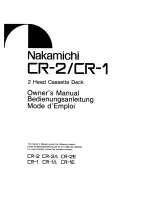
CIRCUIT DIAGRAM - MAIN PART

8-2

8-2

during Focus search

1.9V

1.9V

1.9V

1.9V

1.9V

0V

4V

0V

1.9V

0V

5V

1.9V

10V

5V

5V

4.7V

4V

2.6V

EYE-PATTERN

TB = 0.5us/div

800mVpp

0V

4V

3.3ms

SCLK

TOC-reading

only during

CD-TEXT INFO

DQSY

SRDT

4V

3.8V

3.8V

opt_out version

opt_out version not for 

only for

V

play mode

DC voltages
measured in

3.8V

10V

10V

3.8V

VGAP

OFF

ON/

IREF

SUPPLY

6

5

4

3

1

2

+

-

+

-

+

-

+

-

INTERFACE

EBU

INTERFACE

RAM

ADDRESSER

AUDIO

PROCESSOR

SRAM

FLAGS

ERROR

CORRECTOR

DECODER

MICRO-

PROCESSOR

INTERFACE

SUBCODE

PROCESSOR

VERSATILE PINS

INTERFACE

MICRO

PROCESSOR

INTERFACE

FRONT END

TEST

TIMING

DIGITAL

PLL

EFM

PRE-

PROC.

CONTROL

FUNCTION

OUTPUT STAGES

CONTROL

PART

VREF

GENERATOR

ADC

DEMODULATOR

MOTOR

CONTROL

KILL

PEAK

DETECT

SERIAL DATA

PROTECTION

TIMING & SYNC

CHECK

CRC

INTERF

CPU

RAM

2 PORT

32 x 8

CdCarSw

SelPLL

to servo drivers 

15

A

B

C

D

E

F

G

H

I

A

B

C

D

E

F

G

H

I

1800 E1
1801 G1
1802 D15
1803 B1
1804 A1

1

2

3

4

5

6

7

8

9

10

11

12

13

14

15

1

2

3

4

5

6

7

8

9

10

11

12

13

14

dig. out circuitry

1810 G10
1820 B14
1821 A14
2802 D6
2804 D2

2807 B5
2808 D8
2809 G5
2810 B5
2812 C5

2813 D5
2814 F2
2815 F3
2816 F3
2817 A4

2818 A5
2819 B6
2820 B7
2821 B7
2823 F9

2824 F9
2825 F9
2826 E14
2827 D14
2828 D12

2829 D8
2830 D8

TRACK

2831 C12
2832 C11
2833 G10

2834 G9
2835 H7
2836 H7
2837 G5
2838 F5

2839 F5
2840 F5
2841 I6
2842 I5
2843 H5

2844 H6
2845 H5
2846 G6
2847 G5
2848 D8

2849 D7
2850 C12
2851 D7
2852 D8
2853 B11

2854 D14
2855 C11
2856 D14
2859 E14

For Non-CD Text Version

2860 A14

2861 G14
2862 E5
2863 A7
3801 C7
3802 E6

3803 C7
3804 E5
3805 B7
3806 C7
3807 B7

3808 B7
3809 D2
3810 D2
3812 F3
3813 E7

3814 B7
3815 A8
3816 A6
3817 A6
3818 A7

3820 A11
3821 A11
3822 B11
3823 B11
3824 B11

3825 E8
3829 A13

SLIDE

Carousel

CdDisPosSw

at 3837

3832 B13
3834 B13
3835 A13

3836 A13
3837 H7
3838 H7
3839 F6
3840 F6

3841 F6
3842 I6
3843 I6
3844 I5
3845 H6

3846 H6
3847 H5
3848 G6
3849 G6
3850 G6

3851 C11
3852 F6
3853 H5
3854 E14
3855 C12

3857 C12
3858 C13
3859 C13
3860 C13
3861 D14

3864 D14
3865 F14
3866 F14
3868 F14
3869 F15

3870 G15
3871 G14
3872 H11
3873 D13
3874 F9

3875 G10
3876 G9
3877 C11
3878 F9
3879 E10

3880 D11
3881 A13
3882 E15
3883 F15

CD TEXT

kill circuitry

to

3884 G14

3885 A7
3886 D15
5801 A5
5802 A6
5803 C15

7801 B4
7802 A8
7803 D11
7805 A12
7806 H5

7807 F4
7808 E5
7810 A6
7811 A5
9812 G11

9815 F14

Provision For CD Text

176.4kHz

11.29MHz

FOCUS

To

TURNTABLE

*

5CDC-MG-RW SERVO/DECODER

DECODER

to Kill circuitry

LaserOn

Motor

A

3.8V

(7806,7807)

To DM81

8.46MHz

A

D

+4servo

3816

100R

3R3

3852

3861

100R

3859

470R

D

2860

D

1820

3808

10K

2847

100n

D

2807

22p

2833

2854

100p

3878

100K

D

47n

2820

10n

2828

100n

2819

EBU

47n

2825

470R

3820

+4V

2850

1n

L

D

7

16

13

OUT1-

9

12

5

3

4

8

11

15

2851

220p

2

7811
L7805

8

9

+10V

L

3839

100n

47R

3804

2855

100n

S

100R

3802

5803

2u2

3812

1K

D

100R

3884

LC89170M

1810

CST

8M467

D

3885

15K

47n

2853

D

2859

+4V

L

2843

47u

2826

S

3821

470R

D

220p

2829

D

L

L

DA

SelPLL

V4

+4V

1802

CarMotor

3853

3R3

D

D

D

680R

8K2

4u7

2862

L

+4V

L

V2

V4

QuickPlay

33R

3851

2808

3866

470R

10K

3814

+5V

+4V

150K

3840

6K8

3841

L

3875 1M

S

EH-B

1803

+4V

3835

10K

L

Load

8K2

DA

DA

+4V

330K

3880

1n

2844

S

V1

1801

EH-B

L

220p

470R

3886

3810

4K7

2849

D

22K

3815

S

M

1K

100n

D

100n

2821

D

DA

560R

3844

47u

2836

2842

47R

3836

EBU

10n

47n

2813

3848

9812

EBU_GND

D

S

EBU_GND

22

23

24

25

3

4

5

6

7

8

9

L

5597-NAPB

1

10

11

12

13

14

15

16

17

18

19

2

20

21

10n

2845

3847

D

10K

3803

L

3843

8K2

3854

470R

3865

D

+4V

10R

D

22n

2824

470R

3860

100n

2835

3849

47p

2856

D

D

3825

2830

220p

2n2

2852

3818

560R

L

1n5

M

L

4u7

2832

1K

3838

220p

33R

3873

22K

3857

1821

2u2

5802

L

L

47u

2818

8K2

3846

47p

2861

47u

V2

22n

2846

470R

3850

2815

100n

+4V

3807

10K

4K7

3881

D

3817

560R

+5V

2848

100n

2809

3883

470R

3882

470R

3805

10K

D

S

2817

47u

1

2

3

4K7

3813

1

1A

2

1Y

3

2A

4

2Y

5

3A

6

3Y

9

4A

8

4Y

11

5A

10

5Y

13

6A

12

6Y

7

GND

14

VCC

470R

3855

7802

PC74HCU04D

3834 470R

DA

3845

10K

D

5597-NAPB

1800

1

10

11

12

2

3

4

5

6

7

+10V

100R

D

330R

3874

100n

L

3864

100R

3877

2840

2838

10K

3870

100n

L

DA

10K

3842

22K

3871

10K

D

47n

9815

3806

2u2

5801

100n

2827

L

L

470R

3822

4

8

11

15

2802

4u7

TDA7073

14

10

2

1

6

7

16

OUT1-

13

9

12

5

3

+5V

+5V

7807

BC337-40

7808

100n

2814

470R

3832

L

19

11

6

32 39 49 56

1 12 16

46

29

35
36

37

38

44

58

62 63 42 41 40

30 47 59

2

34

55

8
9

26

53

57

52

48

51

13

54

28

20

60

23

4 5 7

45

31

27

15
17

18

10

14

43

64

33

SAA7378

7803

61

25

24

50

21
22

3

XH-B

1

2

3879

22K

3872

4K7

+4V

1804

D

2816

100n

7806

TDA7073

14

10

2

1

6

1K

3837

V1

D

Load

CarMotor

2831

4u7

47p

2823

+10V

+10V

1n

2841

9

VDD 18

VDDL

8

2804

10n

QuickPlay

I2

22 I3

24 I4

20 I5

23 I6

7

LDON

16

LO

12 LS

17

MI

4

O1

6

O2

3

O3

1

O4

5

O5

2

O6

RF

10

RFE

TDA1302T

7801

14

ADJ

C

13

15

GND

11 HG

21 I1

19

220p

DA

10K

3801

S

150K

3829 470R

3823

470R

470R

3868

22K

2839

3824

BC547B

7810

47u

2837

1

2

3

4

5

6

EBU_GND

560p

3809

120K

+4servo

3869

10K

2810

2834

22p

470R

3858

47n

2812

WFCK

6 XMODE

2863

18p

+5V

7805

13

DQSY

1

EXCK

7

GND

5 MCK

2 SBSO

11

SCLK

3 SCOR

12

SRDT

9

SW1

10

SW2

8

TEST

14

VDD

4

L

3876

10K

SILD

KILLL

KILLR

PORE

SDA

SCL

VDD

VDD

Содержание CDC775/00

Страница 1: ...gram 5 Supply Headphone Boards 6 Front Board 7 Servo Decoder Board 8 DAC AF Board 9 Mechanical Exploded views parts list 10 Copyright 1999 Philips Consumer Electronics B V Eindhoven The Netherlands All rights reserved No part of this publication may be reproduced stored in a retrieval system or transmitted in any form or by any means electronic mechanical photocopying or otherwise without the prio...

Страница 2: ...monic Distortion at 1kHz 0 004 Channel unbalance at 1kHz 1dB Channel separation at 1kHz 95dB 1 Headphone impedance 30 600 ohm Headphone output e m f 4 5Vrms 2dB Digital Output at 75ohm 0 5V 1 with 13th order Filter eg 4822 395 30204 LOCATION OF PC BOARDS S E R V O D E C O D E R B O A R D Load QP Board D A C A F B O A R D S U P P L Y B O A R D FRONT BOARD Open close Board H PBOARD 00 01 14 17 CC DA...

Страница 3: ...22 395 10216 Eccentricity Disc 150µm 4822 397 30279 Others 13th Order Filter 4822 395 30204 ESD Equipment Anti static table mat large 1200x650x1 25mm 4822 466 10953 Anti static table mat small 600x650x1 25mm 4822 466 10958 Anti static wristband 4822 395 10223 Connector box 1MΩ 4822 320 11307 Extension cable to connect wristband to conn box 4822 320 11305 Connecting cable to connect table mat to co...

Страница 4: ... di non osservazione della più grande cauzione alla loro manipolazione Durante le riparazioni occorre quindi essere collegato allo stesso potenziale che quello della massa dell apparecchio tramite un braccialetto a resistenza Assicurarsi che i componenti e anche gli utensili con quali si lavora siano anche a questo potenziale Pour votre sécurité ces documents doivent être utilisés par des spécia l...

Страница 5: ...al amount of heat RECEIVER CD CHANGER CASSETTE DECK Introduction 4 Installation 4 5 Functional Overview 6 8 Playback 9 13 Programming 13 Edit 14 15 Additional Information 15 16 Troubleshooting 16 CONTENTS INTRODUCTION INSTALLATION Connections 1 Digital Out This output supplies digital signal and can therefore only be connected to an input which is suitable for this signal Use here a lead with one ...

Страница 6: ... STOP PLAY OPEN CLOSE MAX MIN FADE REPEAT CDC 775 COMPACT DISC CAROUSEL CHANGER CD REWRITABLE COMPATIBLE MULTI DISC CHANGER DIGITAL OUTPUT 1 23 4 5 6 7 8 0 9 TRACK PEAK TOT REM TRACK TIME SHUFFLE PAUSE REPEAT DISC 5 4 1 3 2 PROGRAM 1 LEVEL PHONES IR SENSOR TRACK PEAK TOT REM TRACK TIME SHUFFLE PAUSE REPEAT DISC PROGRAM 5 4 1 3 2 1 Remote Control 1 PAUSE Interrupting play 2 SCAN Automatically playi...

Страница 7: ...ny CDs there are in the CD compartment The turntable will rotate slowly until all positions 1 5 in the CD compartment have been checked The position which is being checked is always shown on the display dISC X After CD detection the 1 5 CD number indicator will show the number of CDs in the CD compartment Open the CD compartment by pressing OPEN CLOSE OPEN lights up Insert the CDs printed side up ...

Страница 8: ... PLAYBACK Playing In Random Order SHUFFLE All CDs Press SHUFFLE before or during play If the CD compartment was open it will now close SHUFFLE lights up and all the tracks are now played in a random order If you press T you will select any one of the following tracks Press SHUFFLE again if you wish to return to normal play NOTE If during play you open the CD compartment to change CDs see NORMAL PL...

Страница 9: ... the display shows VOL LOCK it means that the volume is in the lock mode Listening to the heaphones Connect the headphones to the PHONES socket Adjust the headphones sound level with the LEVEL control Note Should there be no sound after adjusting the LEVEL control to maximum press VOLUME on the remote control to increase the sound level TRACK PEAK TRACK TIME 1 TRACK TRACK TIME REPEAT 1 12 English ...

Страница 10: ...ding time The CD changer will now go back to STOP mode You can now record the CD or the program Recording Press PLAY 2 Playback starts with the selected CD or with the first track of the program The display shows the elapsed playing time of the current track Press TIME to switch to other time display information The number of tracks for side A and their playing time are shown on the display After ...

Страница 11: ...ent CD PRG program or SHUFFLE activated Switch off SHUFFLE or clear program No sound or bad sound Loose or wrong connections Check connections Strong magnetic fields near the CD changer Find another place for the unit or change connections No sound or bad sound on headphones Volume control on remote control is at minimum Increase the volume control level Level control set to position Set level con...

Страница 12: ... remove the CDM Lock pos 99 by using a minus screw driver to release 2 catches C4 as indicated 4 With the Tray assembly facing up again turn the cam wheel pos 116 to bring the CD mechanism pos 98 to the down position Remove the CD mechanism by sliding out the 4 rubber suspension pos 104 to 107 Dismantling of the DAC AF board Supply board and Front Panel Assembly 1 Remove the Top Cover pos 151 by 8...

Страница 13: ...g the CD Mechanism Warning Charged capacitors on the Servo board may damage the CD drive electronics when connecting a new CD mecha nism That s why besides the safety measures like Switch off power supply ESD protection Additional actions must be taken by the repair techni cian The following steps have to be done when replacing the CD Mechanism 1 Disconnect the old CD mechanism flexfoil from print...

Страница 14: ... the carousel is blocked in between two disc positions The time out is approximately 5 seconds The carousel position switch did not close within a certain time This can happen when the switch is defective and never closes electrically or when the carousel is blocked in between two disc positions The time out is approximately 5 Sec The drawer could not enter the inside position and is opening again...

Страница 15: ...ecomes DISC OK Display remains as DISC ERR Disc Motor Test Display shows DISC Sledge Motor Test CD_X Button pressed Y Change to selected disc N Changer Mechanism Test CD_X refers to CD1 CD2 or CD3 OPEN CLOSE Button pressed Y Close Tray N Tray Motor Test Is tray closed Y N Open Tray SHUFFLE Button pressed Y PROGRAM Button pressed Y N Disc Motor turns Counter Clockwise Display shows CCW Disc Motor t...

Страница 16: ...4 1 PCS 101 019 4 1 SET BLOCK DIAGRAM µP FTD 3139 119 30820 dd wk8530 ...

Страница 17: ...5 1 PCS 101 020 5 1 SET WIRING DIAGRAM CONTROL DISPLAY PANEL HP PANEL TRAY LOADER POWER SUPPLY H T C TRANSFORMER S D DAC AF SERVO DECODER L P 3139 119 30820 dd wk 852 ...

Страница 18: ...HP R GND 3380 D 1 3380 B 1 2383 A 6 2382 D 5 2381 B 5 2380 A 1 1372 A 6 1372 A 6 1371 B 6 1370 C 1 1370 C 1 1370 B 1 1370 A 1 1370 A 1 7380 D 4 7380 B 4 3386 B 4 3385 D 4 3384 A 3 3383 C 3 3382 B 3 3381 D 3 4 5 6 1 2 3 A D C B A D C B 4 5 6 1 2 3 22n 2380 10n 2381 10n 2382 100n 2383 1371 1 2 3 10V 10V 10V 10V 15k 3384 120R 3386 10k 3382 10k 3381 15k 3383 120R 3385 7 5 6 8 4 7380 7380 1 3 2 1370 5 ...

Страница 19: ... WHITE GREEN 240V 220V 230V 0V VFTD ACF2 ACF1 AC2 GND AC1 GREEN RED RED WHITE WHITE BLUE BROWN BLUE BLACK WHITE WHITE GREEN BLUE RED RED BLACK BLUE BROWN BLUE RED RED BLUE BROWN VFTD ACF2 ACF1 AC2 GND AC1 GREEN RED RED WHITE WHITE BLUE BLUE 130 C o THERMAL FUSE NOT SERVICEABLE 0V BROWN 130 C o THERMAL FUSE NOT SERVICEABLE 01 VERSION 240V 220V 230V 0V VFTD ACF2 ACF1 AC2 GND AC1 GREEN RED RED WHITE ...

Страница 20: ... 2509 4822 124 81151 22µF 20 50V 2510 4822 123 14025 2200µF 20 16V 2544 4822 126 10454 3 3nF 20 400V 2560 4822 124 40849 330µF 20 16V RESISTORS 3380 4822 101 21199 Potm Rotary 10k x 2 20 3381 4822 116 83864 10k 5 0 5W 3382 4822 116 83864 10k 5 0 5W 3383 4822 116 52244 15k 5 0 5W 3384 4822 116 52244 15k 5 0 5W 3385 4822 116 52206 120R 5 0 5W 3386 4822 116 52206 120R 5 0 5W 3560 4822 050 11002 1k 1 ...

Страница 21: ...9 P10 P11 P12 1G 3G 2G 5G 4G 6G 7G 8G a b f j k g c e p n d a b f j Dp g c e p n d a b f j g c e p n d a b f j Col g c e p n d a b f j k g c e p n d a b f j g c e p n d 5 4 1 3 2 PROGRAM FTS SHUFFLE PAUSE REPEAT DISC G TRACK PEAK TOT REM TRACK TIME CD VIDEO I 1 7G LCD DISPLAY PIN CONNECTIONS 8G 1G 2G 3G 4G 5G 6G FTS TRACK PEAK TOT REM TRACK TIME SHUFFLE PAUSE REPEAT DISC PROGRAM 5 4 1 3 2 1 VIDEO ...

Страница 22: ...418 BC857B 7410 22n 2418 1K 3412 4K7 3446 7411 BC857B 3459 4K7 2403 100u 4K7 3463 DIPMATE 42 1 2 1K 3419 3432 1K 220p 2414 1418 1K 3423 100n 2408 33p 2405 9480 1K2 3450 3416 1K 3430 1K 2404 22n 1408 3 4 100R 2K2 3451 1411 1K 3406 3K9 3437 3405 1K TEST 33 VDD 66 VKK 15 VSS 13 XIN 14 XOUT 4R7 3402 57 P87 58 P90 59 P91 60 P92 61 P93 62 P94 63 P95 64 P96 65 P97 12 RESET 9 P74 47 P75 48 P76 49 P77 50 P...

Страница 23: ...or components used in a specific version see schematic diagram and respective parts list This assembly drawing shows a summary of all possible versions For components used in a specific version see schematic diagram and respective parts list 1413 A2 1 2 1 2 A 43 A1 43 DIPMATE 1 2 1413 A CIRCUIT LAYOUT OPEN CLOSE PART ...

Страница 24: ... 680R 5 0 1W 3435 4822 117 11454 820R 1 0 1W 3436 4822 051 20122 1k2 5 0 1W 3437 4822 116 52276 3k9 5 0 5W 3438 4822 051 20681 680R 5 0 1W 3439 4822 117 11454 820R 1 0 1W 3440 4822 116 52207 1k2 5 0 5W 3441 4822 051 20392 3k9 5 0 1W 3442 4822 051 20681 680R 5 0 1W 3443 4822 117 11454 820R 1 0 1W 3444 4822 051 20122 1k2 5 0 1W 3445 4822 117 11449 2k2 1 0 1W 3446 4822 051 20472 4k7 5 0 1W 3447 4822 ...

Страница 25: ...ENTS Circuit diagram layout Load Quick Play part 8 1 Circuit diagram Main part 8 2 Component Chip layouts Main part 8 3 Electrical parts list 8 4 8 1 1 2 3 1 2 3 A 1805 A1 1840 A2 1841 A2 1840 1841 1805 EH B 1 2 3 A CIRCUIT DIAGRAM LAYOUT LOAD QP PART ...

Страница 26: ...CODER DECODER to Kill circuitry LaserOn Motor A 3 8V 7806 7807 To DM81 8 46MHz A D 4servo 3816 100R 3R3 3852 3861 100R 3859 470R D 2860 D 1820 3808 10K 2847 100n D 2807 22p 2833 2854 100p 3878 100K D 47n 2820 10n 2828 100n 2819 EBU 47n 2825 470R 3820 4V 2850 1n L D 7 16 13 OUT1 9 12 5 3 4 8 11 15 2851 220p 2 7811 L7805 8 9 10V L 3839 100n 47R 3804 2855 100n S 100R 3802 5803 2u2 3812 1K D 100R 3884...

Страница 27: ...ws a summary of all possible versions For components used in a specific version see schematic diagram and respective parts list This assembly drawing shows a summary of all possible versions For components used in a specific version see schematic diagram and respective parts list ...

Страница 28: ...120k 5 0 1W 3810 4822 051 20472 4k7 5 0 1W 3812 4822 051 10102 1k 2 0 25W 3813 4822 051 20472 4k7 5 0 1W 3814 4822 116 83864 10k 5 0 5W 3815 4822 051 20223 22k 5 0 1W 3816 4822 051 20101 100R 5 0 1W 3817 4822 051 20561 560R 5 0 1W 3818 4822 116 52226 560R 5 0 5W 3825 4822 050 11002 1k 1 0 4W 3837 4822 051 10102 1k 2 0 25W 3838 4822 051 10102 1k 2 0 25W 3839 4822 051 20154 150k 5 0 1W 3840 4822 051...

Страница 29: ...9 1 PCS 101 032 DAC AF BOARD TABLE OF CONTENTS Notes 9 1 Circuit diagram 9 2 Component Chip layouts 9 3 Electrical parts list 9 4 9 1 Notes ...

Страница 30: ...tal out circuitry 5B GNDA 10V 22n 2892 BC857B 7837 47u 2897 9930 7 8 9 EBU_GND D 2K2 3937 D L7805 7831 2 10K 3961 10V 3R3 3918 GNDA 5V 10K 3976 D 47u 2899 CarMotor D GNDA 4 3 3919 3R3 3940 1K GNDA 5V D 47u 2896 M 3952 10V L GNDA 2885 100n D GNDA 5V 2888 470p 22R 3947 3934 22K EBU_GND D 10V KILL2 47K 3970 GNDA M 2926 150p GNDA EVQ21 1843 S EH B 1833 2887 47u 2 1 8 4 22K 3902 7839 BC817 25 10R 3960 ...

Страница 31: ...summary of all possible versions For components used in a specific version see schematic diagram and respective parts list This assembly drawing shows a summary of all possible versions For components used in a specific version see schematic diagram and respective parts list ...

Страница 32: ...934 4822 051 20223 22k 5 0 1W 3935 4822 051 10102 1k 2 0 25W 3936 4822 051 10102 1k 2 0 25W 3937 4822 117 11449 2k2 1 0 1W 3938 4822 117 11449 2k2 1 0 1W 3939 4822 051 10102 1k 2 0 25W 3940 4822 051 10102 1k 2 0 25W 3941 4822 117 11449 2k2 1 0 1W 3942 4822 117 11449 2k2 1 0 1W 3943 4822 117 11383 12k 1 0 1W 3945 4822 117 11383 12k 1 0 1W 3946 4822 117 11383 12k 1 0 1W 3947 4822 052 10229 22R 5 0 3...

Страница 33: ...10 1 PCS 101 036 EXPLODED VIEW FRONT PART 10 1 ...

Страница 34: ...10 2 PCS 101 037 EXPLODED VIEW REAR PART 10 2 ...

Страница 35: ...10 3 PCS 101 038 EXPLODED VIEW CDC5 LOADER 10 3 ...

Страница 36: ...93132 Guide 93 141 4822 466 93132 Guide 93 142 4822 466 93132 Guide 93 144 4822 528 50334 Pulley 95 4822 522 33255 Gearwheel 96 4822 402 11241 Crank CDC5 98 4822 691 10615 CD Mechanism VAM1201 99 4822 403 70598 CDM Lock 100 4822 466 93129 Rotary Disc Assembly 101 4822 520 20758 Bearing 103 4822 401 11447 Tray Tumbler 104 4822 404 10986 Suspension Rubber 105 4822 404 10986 Suspension Rubber 106 482...

Страница 37: ...Service Audio Printed in The Netherlands Subject to modification GB 3139 785 22200 PCS 103 371 Service Service Service CDC775 00G 01G 14G 17G CLASS 1 LASER PRODUCT COMPACT DIGITAL AUDIO CD Changer Introduction of CDC775 00G 01G 14G 17G For Service documentation please refer to Service Manual CDC775 4822 725 25851 1 CDC775 00G refers to CDC775 00 2 CDC775 01G refers to CDC775 01 except 387 3139 116...

Отзывы: