Alignments
6.
6.
Alignments
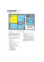
Index of this chapter:
6.1 General Alignment Conditions
6.2 Hardware Alignments
6.3 Software Alignments
6.4 Option Settings
6.5 Reset of Repaired SSB
6.1
General Alignment Conditions
Perform all electrical adjustments under the following
conditions:
•
Power supply voltage: 90 - 264 V
AC
, 50/ 60 ± 3 Hz.
•
Connect the set to the mains via an isolation transformer
with low internal resistance.
•
Allow the set to warm up for approximately 15 minutes.
•
Measure voltages and waveforms in relation to correct
ground (e.g. measure audio signals in relation to
AUDIO_GND).
Caution: It is not allowed to use heat sinks as ground.
•
Test probe: R
i
> 10 MW, C
i
< 20 pF.
•
Use an isolated trimmer/screwdriver to perform
alignments.
6.2
Hardware Alignments
Not applicable.
6.3
Software Alignments
Put the set in SAM mode (see Chapter
). The SAM menu will now appear on
the screen. Select RGB Align and go to one of the sub menus.
The alignments are explained below.
The following items can be aligned:
•
White point.
To store the data:
•
Press OK on the RC before the cursor is moved to the
left.
•
Select “Store” and press OK on the RC.
•
Switch the set to stand-by mode.
For the next alignments, supply the following test signals via a
video generator to the RF input:
•
EU/AP-PAL models: a PAL B/G TV-signal with a signal
strength of at least 1 mV and a frequency of 475.25 MHz
•
US/AP-NTSC models: an NTSC M/N TV-signal with a
signal strength of at least 1 mV and a frequency of
61.25 MHz (channel 3).
•
LATAM models: an NTSC M TV-signal with a signal
strength of at least 1 mV and a frequency of
61.25 MHz (channel 3).
6.3.1
RGB Alignment
Before alignment, set the picture as follows:
White Tone Alignment:
•
Activate SAM.
•
Select “RGB Align.” and choose a color temperature.
•
Use a 100% white screen as input signal and set the
following values:
–
“Red BL Offset” and “Green BL Offset” to “7” (if
present).
–
All “White point” values initial to “128”.
In case you have a colour analyser:
•
Measure with a calibrated (phosphor- independent) color
analyser (e.g. Minolta CA-210) in the centre of the screen.
Consequently, the measurement needs to be done in a
dark environment.
•
Adjust the correct x, y coordinates (while holding one of the
White point registers R, G or B on max. value) by means of
decreasing the value of one or two other white points to the
correct x, y coordinates (see Table
). Tolerance: dx: ± 0.003, dy: ± 0.003.
•
Repeat this step for the other colour Temperatures that
need to be aligned.
•
When finished return to the SAM root menu and press
STANDBY on the RC to store the aligned values to the
NVM.
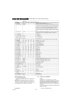
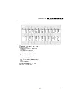
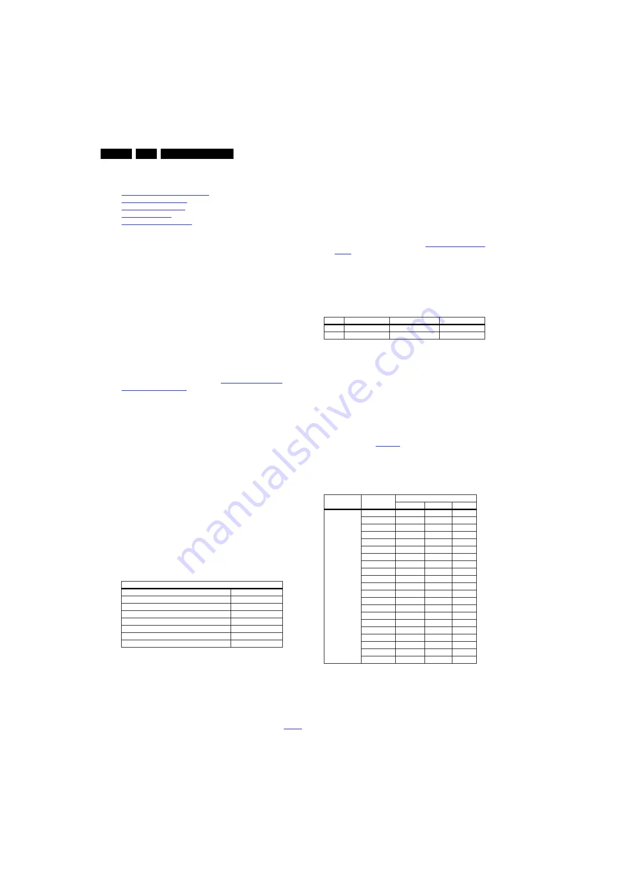
Table 6-1 White D alignment values
If you do not have a colour analyser, you can use the default
values. This is the next best solution. The default values are
average values coming from production (statistics).
6.3.2
Display Adjustment
You can use the default values. The default values are average
values coming from production.
•
Enter SAM mode.
•
Select a colour temperature (e.g. COOL, NORMAL, or
WARM).
•
Set the RED, GREEN and BLUE default values according
to the values in
.
•
When finished press OK on the RC, then press STORE to
store the aligned values to the NVM.
•
Restore the initial picture settings after the alignments.
Table 6-2 White tone default settings
Picture Setting
Dynamic backlight
Off
Dynamic Contrast
Off
Color Enhancement
Off
Picture Format
Unscaled
Light Sensor
Off
Brightness
50
Color
0
Contrast
100
Value
Cool (11000 K)
Normal (9000 K)
Warm (6500 K)
x
0.276
0.287
0.313
y
0.282
0.296
0.329
Picture mode
Screen size
Colour temperature
Red
Green
Blue
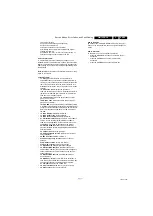
Normal (9000K)
43PUT6801/98
112
121
116
43PUT6801/56
110
120
117
43PUT6801/79
112
122
116
49PUT6801/98
109
111
115
49PUT6801/56
108
112
114
49PUT6801/79
107
113
113
55PUT6801/98
105
108
106
55PUT6801/56
108
107
104
55PUT6801/79
106
105
106
55PUT7101/98 120
115
108
55PUT7101/79 121
114
107
55PUT7101/56 122
114
107
65PUT7101/79 117
119
118
65PUT7101/98 116
118
118
65PUT7101/56 115
117
116
65PUT7601/98 126
80
43
65PUT7601/79 125
82
45
65PUT7601/56 124
83
47
75PUT7101/79 116
120
121
75PUT7101/98 118
120
123
75PUT7101/56 117
121
122

