Service Modes, Error Codes, and Fault Finding
5.
5.4.6
Content and Usage of the One-Zip Software File
Below you find a content explanation of the One-Zip file, and
instructions on how and when to use it. Only files that are
relevant for Service are mentioned here.
•
EDID_clustername.zip: Contains the EDID content of the
different EDID NVMs.
•
FUS_clustername_version.zip: Contains the file
downloaded which is needed to upgrade the TV main
software and the software download application.
•
NVM_clustername_version.zip: Default NVM content.
5.4.7
How to Copy NVM Data to/from USB
When copying data to and from a USB memory stick, the folder
“repair” is used. When inserting an empty USB memory stick,
and downloading data to the stick, the TV will create this folder.
When sending data from a USB memory stick to a TV, the
intended data must be available in the “repair” folder.
Note that when copying EDID data to the TV, all necessary
EDID files must be in this folder.
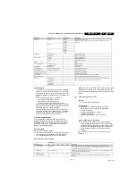
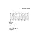
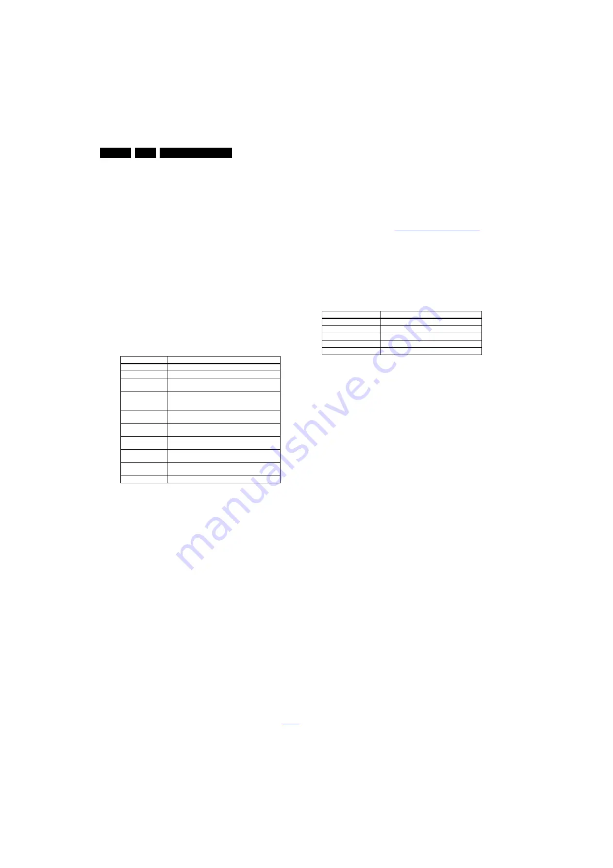
Service mode overview for your reference.
Table 5-3 Service mode overview
5.5
Error Codes
5.5.1
Introduction
Error codes are required to indicate failures in the TV set. In
principle a unique error code is available for every:
•
Activated (SW) protection.
•
Failing I
2
C device.
•
General I
2
C error.
The last five errors, stored in the NVM, are shown in the
Service menu’s. This is called the error buffer.
The error code buffer contains all errors detected since the last
time the buffer was erased. The buffer is written from left to
right. When an error occurs that is not yet in the error code
buffer, it is displayed at the left side and all other errors shift one
position to the right.
An error will be added to the buffer if this error differs from any
error in the buffer. The last found error is displayed on the left.
An error with a designated error code never leads to a
deadlock situation. It must always be diagnosable (e.g. error
buffer via OSD or blinking LED).
In case a failure identified by an error code automatically
results in other error codes (cause and effect), only the error
code of the MAIN failure is displayed.
5.5.2
How to Read the Error Buffer
You can read the error buffer in three ways:
•
On screen via the SAM/CSM (if you have a picture).
Example:
–
ERROR: 000 000 000 000 000: No errors detected
–
ERROR: 013 000 000 000 000: Error code 13 is the
last and only detected error
–
ERROR: 034 013 000 000 000: Error code 13 was
detected first and error code 34 is the last detected
(newest) error
•
Via the blinking LED procedure (when you have no
picture). See paragraph
5.7 Fault Finding and Repair Tips
.
5.5.3
Error codes
In this chassis only “layer 2” error codes are available and point
to problems on the SSB. They are triggered by LED blinking
when CSM is activated. Only the following layer 2 errors are
defined:
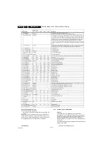
Table 5-4 Error code table
5.5.4
How to Clear the Error Buffer
The error code buffer is cleared in the following cases:
•
By using the CLEAR command in the SAM menu
•
By using the CLEAR command in the Factory mode:
•
By using the following key sequence on the remote control
transmitter: “062599” directly followed by the OK button.
•
If the contents of the error buffer have not changed for 50
hours, the error buffer resets automatically.
Note: If you exit SAM by disconnecting the mains from the
television set, the error buffer is not reset.
5.6
The Blinking LED Procedure
5.6.1
Introduction
The software is capable of identifying different kinds of errors.
Because it is possible that more than one error can occur over
time, an error buffer is available, which is capable of storing the
last five errors that occurred. This is useful if the OSD is not
working properly.
Errors can also be displayed by the blinking LED procedure.
The method is to repeatedly let the front LED pulse with as
many pulses as the error code number, followed by a period of
1.5 seconds in which the LED is “off”. Then this sequence is
repeated.
Example (1): error code 4 will result in four times the sequence
LED “on” for 0.25 seconds / LED “off” for 0.25 seconds. After
this sequence, the LED will be “off” for 1.5 seconds. Any RC
command terminates the sequence. Error code LED blinking is
in red color.
Example (2): the content of the error buffer is “12 9 6 0 0” After
entering SAM, the following occurs.
•
1 long blink of 5 seconds to start the sequence.
•
12 short blinks followed by a pause of 1.5 seconds.
•
9 short blinks followed by a pause of 1.5 seconds.
•
6 short blinks followed by a pause of 1.5 seconds.
•
1 long blink of 1.5 seconds to finish the sequence.
•
The sequence starts again with 12 short blinks.
5.6.2
How to Activate Blinking LED Procedurer
Use one of the following methods:
•
Activate CSM.The blinking front LED will show the layer 1
error(s), this works in “normal operation” mode or
Service Modes
Description
SAM
Service alignment mode
Factory Mode
Used for extended alignments
CSM
3-page compact CSM pages. There will be CSM dump to
USB-stick upon entering CSM-mode
USB SW upgradeable SW-upgrading of flash memories MT5593UGIJ can be
done via USB. The main SW can be upgraded via the ZIP
file downloaded.
NVM-Editor in SAM
NVM-editor will function as in the past: Address and Value
field is a decimal value via digit entry
Service Data
New Service data in SAM for CTN, Prod. no., 12NC
programming with virtual keyboard
USB copy/paste in
SAM
Channel list, NVM data, Readable info, EDID
UART logging
There will be printout available in UART. No specifications
of the printout, per MTK provision/definition.
Blind SAM
RC sequence “062598” + “Menu” +
“Panel code”
Clear Buffer
RC sequence “062599” + “OK” or via SAM
Layer-2 error code
Defective device
13
General I
2
C bus error on the SSB
16
+12 V missing or low, PSU defective
27
Channel decoder error on the SSB
34
Tuner I
2
C bus error on the SSB
35
EEPROM I
2
C error on SSB, M24C64

