


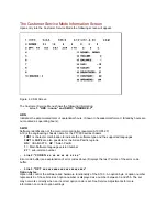


The Customer Service Mode Information Screen
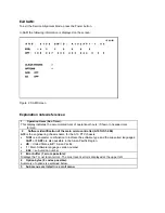
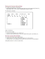
Upon entry into the Customer Service Mode the following screen will appear.
Figure 4: CSM Screen
The Customer Service Menu shows the following information:
-
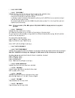
Line 1: “HRS : nnnnn” and SWID : “A10BBC-X.Y”
HRS:
Indicates the accumulated total of operational hours. (Shown in hexadecimal format.) (Standby hours are
not counted as operating hours).
SWID:
Software identification of the main micro controller (example: A10US1-2.7)
A10 is the engineering chassis name for the PTV900 series chassis
·
1US1
is character combination to indicate the software type and the supported languages:
3AP1
or
3AP2
are also possible for the Asian Pacific regions.
·
US
= USA/NAFTA,
AP
= Asian Pacific
·
1
= Main Software language version number
·
2.7
= sub-version number
-
Line 2: “CODES: xx xx xx xx xx xx xx ”
Error code buffer (see explanation of error codes above) Displays the last 7 errors of the error code
buffer.
-
Line 3: “OPT xxx xxx xxx xxx xxx xxx xxx xxx”
Option bytes
Option bits control the software and hardware functionality of the A10.0. An option byte or option number
represents 8 of those bits. Each option number is displayed as a number between 0 and 255. The set
may not work correctly when an incorrect option code is set. See Service Adjustments for more
information on correct option settings
Содержание 43P 8341
Страница 1: ......
Страница 35: ......
Страница 36: ......
Страница 37: ......
Страница 38: ......
Страница 39: ......
Страница 40: ......
Страница 41: ......
Страница 42: ......
Страница 43: ......
Страница 44: ......
Страница 45: ......
Страница 46: ......
Страница 47: ......
Страница 48: ......
Страница 49: ......
Страница 50: ......
Страница 51: ......
Страница 52: ......
Страница 53: ......
Страница 54: ......
Страница 55: ......
Страница 56: ......
Страница 57: ......
Страница 58: ......
Страница 59: ......
Страница 60: ......
Страница 61: ......
Страница 62: ......
Страница 63: ......
Страница 64: ......
Страница 65: ......
Страница 66: ......
Страница 67: ......
Страница 68: ......
Страница 69: ......
Страница 70: ......
Страница 71: ......
Страница 72: ......
Страница 73: ......
Страница 74: ......
Страница 75: ......
Страница 76: ......
Страница 77: ......
Страница 78: ......
Страница 79: ......
Страница 80: ......
Страница 81: ......
Страница 83: ......
Страница 84: ......
Страница 85: ......
Страница 86: ......
Страница 87: ......
Страница 88: ......
Страница 89: ......
Страница 90: ......
Страница 91: ......
Страница 92: ......
Страница 93: ......
Страница 94: ......
Страница 95: ......
Страница 96: ......
Страница 97: ......
Страница 98: ......
Страница 100: ......
Страница 101: ......
Страница 102: ......
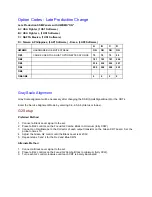
Страница 196: ...Area With IC7407 Removed Step 3 Jumper Legs 13 and 14 Jumper legs 13 and 14 of IC7407 with solder as shown below ...


