


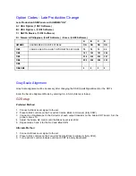


Gray Scale Setup
1. Connect a Gray Scale pattern to the set.
2. Preset the registers as shown below.
NORMAL RED
26
NORMAL GREEN
56
NORMAL BLUE
59
NORMAL BLACK LEVEL RED
10
NORMAL BLACK LEVEL GREEN
13
DELTA COOL RED
-6
DELTA COOL GREEN
-7
DELTA COOL BLUE
4
DELTA COOL BLACK LEVEL RED
2
DELTA COOL BLACK LEVEL GREEN
1
DELTA WARM RED
6
DELTA WARM GREEN
0
DELTA WARM BLUE
-8
DELTA WARM BLACK LEVEL RED
-2
DELTA WARM BLACK LEVEL GREEN
-1
CATHODE DR
12
3. Set Brightness, Color, and Sharpness controls to 40 and Picture control to maximum.
4. Adjust the NORMAL BLACK LEVEL controls to set the correct gray scale in the dark areas of the
picture.
5. Adjust the NORMAL RED AND BLUE controls to set the correct gray scale in the light areas of the
picture.
6. Use the Menu button on the Remote to back out to the main service menu.
7. Turn the set off using the Power Button on the Remote or the front of the set.
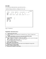
Customer Service Mode (CSM)
All PTV900 series sets are equipped with the “Customer Service Mode” (CSM). CSM is a special service
mode that can be activated and deactivated by the customer, by request of the service technician/dealer
in order to identify the status of the set. This CSM is a 'read only' mode, therefore modifications in this
mode are not possible.
Содержание 43P 8341
Страница 1: ......
Страница 35: ......
Страница 36: ......
Страница 37: ......
Страница 38: ......
Страница 39: ......
Страница 40: ......
Страница 41: ......
Страница 42: ......
Страница 43: ......
Страница 44: ......
Страница 45: ......
Страница 46: ......
Страница 47: ......
Страница 48: ......
Страница 49: ......
Страница 50: ......
Страница 51: ......
Страница 52: ......
Страница 53: ......
Страница 54: ......
Страница 55: ......
Страница 56: ......
Страница 57: ......
Страница 58: ......
Страница 59: ......
Страница 60: ......
Страница 61: ......
Страница 62: ......
Страница 63: ......
Страница 64: ......
Страница 65: ......
Страница 66: ......
Страница 67: ......
Страница 68: ......
Страница 69: ......
Страница 70: ......
Страница 71: ......
Страница 72: ......
Страница 73: ......
Страница 74: ......
Страница 75: ......
Страница 76: ......
Страница 77: ......
Страница 78: ......
Страница 79: ......
Страница 80: ......
Страница 81: ......
Страница 83: ......
Страница 84: ......
Страница 85: ......
Страница 86: ......
Страница 87: ......
Страница 88: ......
Страница 89: ......
Страница 90: ......
Страница 91: ......
Страница 92: ......
Страница 93: ......
Страница 94: ......
Страница 95: ......
Страница 96: ......
Страница 97: ......
Страница 98: ......
Страница 100: ......
Страница 101: ......
Страница 102: ......
Страница 196: ...Area With IC7407 Removed Step 3 Jumper Legs 13 and 14 Jumper legs 13 and 14 of IC7407 with solder as shown below ...


