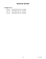
20100630
14-12
A01PCEL
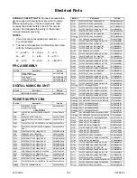
Electrical Parts
PRODUCT SAFETY NOTE:
Products marked with a
#
have special characteristics important to safety.
Before replacing any of these components, read
carefully the product safety notice in this service
manual. Don't degrade the safety of the product
through improper servicing.
NOTES:
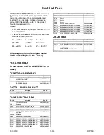
1. Parts that are not assigned part numbers (---------)
are not available.
2. Tolerance of Capacitors and Resistors are noted
with the following symbols.
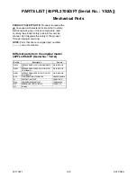
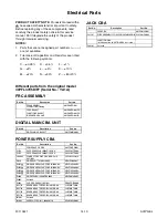
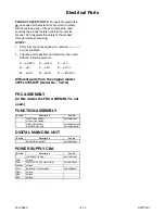
Different parts from the original model
40PFL3705D/F7 (Serial No. : YA1A)
FRC ASSEMBLY
(In this model, the FRC ASSEMBLY is not
used.)
FUNCTION ASSEMBLY
DIGITAL MAIN CBA UNIT
POWER SUPPLY CBA
C.....±0.25%
D.....±0.5%
F.....±1%
G.....±2%
J......±5%
K.....±10%
M.....±20%
N.....±30%
Z.....+80/-20%
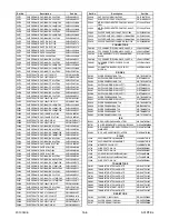
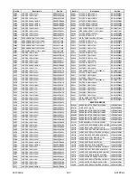
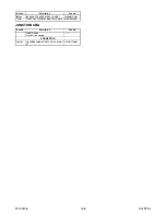
Ref. No.
Description
Part No.
FUNCTION ASSEMBLY
Consists of the following:
A01PCMSW-001
FUNCTION CBA UNIT
IR SENSOR CBA UNIT
A01PCMSW-001-FN
A01PCMSW-001-IR
Ref. No.
Description
Part No.
DIGITAL MAIN CBA UNIT
A01PCMMA-001
Ref. No.
Description
Part No.
POWER SUPPLY CBA
A01P1MPW-001
C658
Not used
C663
ELECTROLYTIC CAP. 470
µ
F/10V M
CE1AMASDL471
CN1803
Not used
D656
DIODE SHOTTKY SB3200BR
NDWZ3200D027
Q654
Not used
R676
Not used
R677
Not used
Содержание 40PFL3505D/F7
Страница 49: ...10 6 PL10 5SCJ1 Jack 1 Schematic Diagram ...
Страница 50: ...10 7 PL10 5SCJ2 Jack 2 Junction Schematic Diagram ...
Страница 51: ...10 8 PL10 5SCF Function Schematic Diagram ...
Страница 52: ...10 9 PL10 5SCIR IR Sensor Schematic Diagram ...

