Service Modes, Error Codes, and Fault Finding
5.
5.
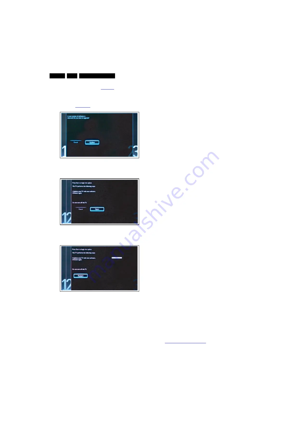
To proceed, in next menu select [Start] and press OK to
start software updates. See
6.
Upgrading will now begins and the status of the updating
progress will be displayed.
7.
When the TV software is updated. Remove your USB flash
drive, then select [Restart] and press OK to restart the
TV.See
Figure 5-8 Update the TV software [1/3]
Figure 5-9 Update the TV software [2/3]
Figure 5-10 Update the TV software [3/3]
Note:
•
Do not remove the USB flash drive during the software
update.
•
If a power failure occurs during the update, do not remove
the USB flash drive from the TV. The TV will continue the
software update as soon as the power comes up again.
•
If an error occurs during the update retry the procedure or
contact the dealer.
•
We do not recommend downgrading to an older version.
•
Once the upgrade is finished, use the PC to remove the TV
software from the USB portable memory.
5.5.6
Content and Usage of the One-Zip Software File
Below you find a content explanation of the One-Zip file, and
instructions on how and when to use it. Only files that are
relevant for Service are mentioned here.
•
FUS_clustername_version.zip: Contains the
“autorun.upg” which is needed to upgrade the TV main
software and the software download application.
•
NVM_clustername_version.zip: Default NVM content.
Must be programmed via ComPair.
5.5.7
How to Copy NVM Data to/from USB
When copying data to and from a USB memory stick, the folder
“repair” is used. When inserting an empty USB memory stick,
and downloading data to the stick, the TV will create this folder.
When sending data from a USB memory stick to a TV, the
intended data must be available in the “repair” folder.
While copying to or from the USB “Repair” Folder to TV, the
files need to be named accordingly:
•
Channel List: CM_TP83L_LA_CK.BIN
•
NVM: NVM_TPM83L_LA_CK.BIN
5.6
Error Codes
5.6.1
Introduction
Error codes are required to indicate failures in the TV set. In
principle a unique error code is available for every.
•
Activated (SW) protection.
•
Failing I
2
C device.
•
General I
2
C error.
The last five errors, stored in the NVM, are shown in the
Service menu’s. This is called the error buffer.
The error code buffer contains all errors detected since the last
time the buffer was erased. The buffer is written from left to
right. When an error occurs that is not yet in the error code
buffer, it is displayed at the left side and all other errors shift one
position to the right.
An error will be added to the buffer if this error differs from any
error in the buffer. The last found error is displayed on the left.
An error with a designated error code never leads to a deadlock
situation. It must always be diagnosable
(e.g. error buffer via OSD or blinking LED or via ComPair).
In case a failure identified by an error code automatically
results in other error codes (cause and effect), only the error
code of the MAIN failure is displayed.
Errors code information:
•
Error 000: No problem.
•
Error 011: I
2
C bus error. When this error occurs, the TV will
not start up due to the blocked bus.
•
Error 012: Tuner error. There is no I
2
C communication
towards the tuner after start-up.
•
Error 013: Panel VCC error. This voltage is made in the
power supply and results in protection in case of absence.
5.6.2
How to Read the Error Buffer
You can read the error buffer in three ways:
•
On screen via the SAM/SDM/CSM (if you have a picture).
Example:
–
ERROR: 0 0 0 0 0: No errors detected.
–
ERROR: 6 0 0 0 0: Error code 6 is the last and only
detected error.
–
ERROR: 9 6 0 0 0: Error code 6 was detected first and
error code 9 is the last detected (newest) error.
•
Via the blinking LED procedure
(when you have no picture). See paragraph
5.7 The Blinking LED Procedure
•
Via ComPair.
19080_207_110324.eps
110324
19080_208_110324.eps
110324
19080_209_110324.eps
110324


