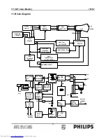
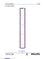

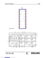
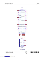


17” CDT Color Monitor 107S7
71
•
Maximum pixel rate -
110 MHz.
•
Sync input -
TTL level, separate H/V sync only, “+” or “-“ polarity,
terminated with
≥
2.2k
Ω
impedance.
•
Horizontal frequency -
30 ~ 71 kHz.
•
Horizontal sync width -
0.6 us minimum, 4 us maximum.
•
Vertical frequency -
50 ~ 160 Hz.
•
Vertical sync width -
2 lines minimum, 10 lines maximum.
•
Analog RGB level -
0 ~ 700mV linear, positive polarity, terminated with 75
Ω
±
5%
impedance.
•
Preset video modes -
8 preset modes. All visual performance has to fulfill the FOS
performance specifications. The user can recall the factory setting
in OSD menu.
•
Preload video modes -
10 preload modes. Parameters preloaded in EEPROM, little size
and centering deviations are allowed, but geometry distortions
should be strictly managed for users easy adjustment. The user can
recall
the
factory
setting
in
OSD
menu.
•
User modes -
6 user modes. User can store adjustment result of 6 new modes,
first in first out control when over 6 new modes are encountered.
•
Detectable mode frequency separation -
± 1kHz min. for H-sync, ± 1Hz min. for V-sync.
2.2.2 Video driver signals
•
Rise time -
< 10ns / 30Vpp (real measurement, white to black)
•
Fall time -
< 10ns / 30Vpp (real measurement, black to white)
•
Overshoot / undershoot -
< 15%
•
Black level shift -
< 5% (30 min ~ 3 hour)
2.3 DDC Signals
•
Support VESA DDC/2B according to VESA DDC standard Ver.1.0 Rev. 3.
•
DDC1 is not allowed.
The DDC components are connected to both monitor Vcc and DDC +5V (from PC via video cable), that the PC can
read the DDC data also when the monitor is powered off. To prevent current feedback into PC, blocking diodes are
required at monitor side.
•
DDC serial Data -
D-sub connector pin 12, I
2
C-BUS.
•
DDC serial Clock -
D-sub connector pin 15, I
2
C-BUS.
Содержание 107S7
Страница 12: ...17 CDT Color Monitor 107S7 12 ...
Страница 18: ...17 CDT Color Monitor 107S7 18 Fig 4 Fig 5 Fig 6 ...
Страница 33: ...17 CDT Color Monitor 107S7 33 8 Mechanical of cabinet front dis assembly ...
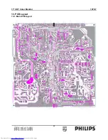
Страница 62: ...17 CDT Color Monitor 107S7 62 13 PCB Layout 13 1 Main PCB layout ...
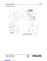
Страница 63: ...17 CDT Color Monitor 107S7 63 13 2 CRPC Board layout ...


