


BK-130
7-1
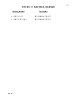
SECTION 7: CALIBRATION
All calibrations have been done at the factory. Periodic calibration of the output voltmeter and output
currentmeter should be done approximately every six months.
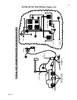
NOTE: Refer to Electrical Diagram Section for schematics pertaining to the model number of your test set.
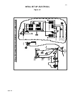
Locating the Calibration Adjustments
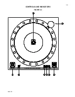
The calibration points are shown in the following diagram.
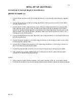
1.
Output Voltmeter
Connect a precision high voltage voltmeter across the output to ground on 36 kV output, with
Measurement Divider switch set to 36 kV. Raise the output to approximately 80% of the output rating.
Adjust the reading on the panel meter (M2) by means of potentiometer R1 to a corresponding reading.
Repeat procedure with precision high voltage voltmeter connected between the 130 kV output and
ground with the Measurement Divider switch set to 130 kV. Adjust R2 to match precision voltmeter at
80% of output rating.
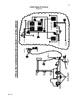
2.
Output Currentmeter
It is necessary to connect adequately rated High Voltage loads (isolated from ground) to the high voltage
unit that will allow each full range current to be drawn at approximately 15% or higher output voltage.
This allows sufficient resolution to adjust current levels. All ranges can be calibrated from 36 kV output.
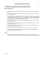
Place Binding Post Configuration in GU
ARD MODE. (Jumper clip is installed between “GRD” and
“GND” posts.)
Connect a precision ammeter between the low potential side of the appropriate high voltage load and
the “RTN” post. Select the 200 uA meter range. Raise the output to approximately 80% of the range
rating. Adjust the reading on the panel meter (M1) by means of potentiometer R204 to a corresponding
reading. Repeat for 2 mA, 20 mA and 200 mA ranges adjusting R203, R202 and R201, respectively.
(High Voltage load will need to change when changing range).
An optional method is to use current injection between RTN and GND (Guard Mode).
Do not turn High Voltage on for this method!
R101
10%
Ovld
R103
110%
Ovld
R235
Range
Ovld
R201
200mA
CM
R202
20mA
CM
R203
2mA
CM
R204
200µA
CM
R2
130 kV
VM
R1
36 kV
VM
CAUTION
:
Calibration should only be done by persons familiar with High Voltage testing and safety
procedures.


