44
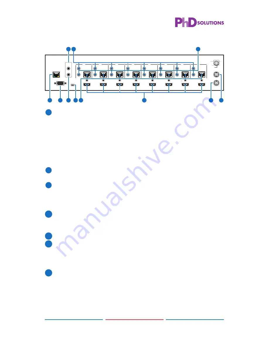
6.2 Rear Panel
RS232
SERVICE
IR OUT
IR IN
IR OUT
IR IN
IR OUT
IR IN
ALL
A
B
C
D
E
F
G
H
CAT5e/6 OUT
IR OUT
IR IN
CAT5e/6 OUT
IR OUT
IR IN
CAT5e/6 OUT
IR OUT
IR IN
CAT5e/6 OUT
IR OUT
IR IN
CAT5e/6 OUT
IR OUT
IR IN
CAT5e/6 OUT
CAT5e/6 OUT
IR OUT
IR IN
CAT5e/6 OUT
MAIN 24V
POE 24V
1
HDMI IN
2
HDMI IN
3
HDMI IN
4
HDMI IN
5
HDMI IN
6
HDMI IN
7
HDMI IN
8
HDMI IN
1
2
3
4
V+
GND
GND
GND
V+
CONTROL
2
4
3
5
10
11
1
6
8
7
9
1
LAN:
Connect to an active network for LAN serving and Telnet and
Web GUI control (refer to Sections 6.8 and 6.9).
When the Matrix or any compatible LAN equipped receivers are
connected to a network, this allows the network access (including
internet access if available) to be shared between the Matrix and
all connected receivers. Connect any Ethernet equipped device
e.g. a Smart TV or games console to the LAN port of a receiver for
that device to share the network/internet access.
2
RS-232:
Connect to a PC or control system with D-Sub 9-pin cable
for the transmission of RS-232 commands.
3
ALL IR OUT:
Connect to the IR blaster for IR signal transmission to
the source side. Place the IR blaster in direct line-of-sight of the
equipment to be controlled for it will blaster out all signal received
from the IR IN at the receiver sides.
4
ALL IR IN:
Connect to the IR extender for IR signal reception. Ensure
that remote being used is within the direct line-of-sight of the IR
extender for it will send out the signal to all receiver's IR OUT.
5
SERVICE:
Manufacturer use only.
6
IR OUT 1~8:
Connect to the IR blasters for IR signal transmission.
Place the IR blaster in direct line-of-sight of the equipment to be
controlled for it will blaster out the IR signal received from the
receiver side choosen by input selection.
7
IR IN 1~8:
Connect to the IR extenders for IR signal reception. Ensure
that remote being used is within the direct line-of-sight of the IR
extender for it will send out the IR signal to the selected receiver's
IR OUT.


