Phason
Installing the RS485-FD Converter
25048008
5
Connecting the communication and common reference wiring
1.
Connect all the devices in series. For example,
A
on the RS485-FD to
A
on the first device, to
A
on the second device, and so on. Use the wires specified in the table on page 2 and follow the
guidelines on page 3.
2.
Remove the termination resistors from each device,
except for the last one on the communication
channel
. The last device
must
have the termination resistors in place. For the location of the
termination resistors, see the installation guide for each specific product.
For controls having only four-position connectors, it is a good idea to leave the
communication cable one foot longer than is needed for connecting to the
terminals (
A
,
B
,
C
, and
D
). You can then use the extra length of wire to connect
to a reference point on the circuit board in place of the
E
terminal.
For information about which terminal to use in place of the
E
terminal, see the
user manual for the specific device, or contact Phason Customer Support.
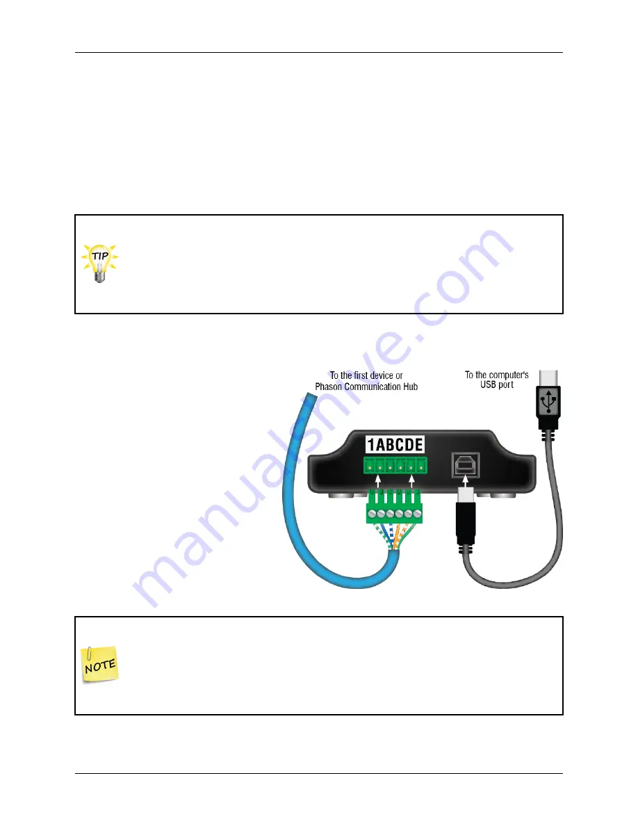
Connecting the RS485-FD to the computer
After connecting the communication
and common reference wiring to all the
devices, connect the RS485-FD to the
computer.
1.
Plug the communication connector
into the communication socket on
the RS485-FD.
2.
Connect the square end of the USB
cable to the RS485-FD and the
rectangular end directly to one of
your computer’s USB ports.
Because of the RS485-FD power requirements, if you are using a USB hub, it
must be one that has an external power supply,
not one powered from the
computer's USB port
.
If this is the first time you have connected the RS485-FD to the computer, your
operating system will tell you that it has detected new hardware and ask to
install the drivers. Read the next section before installing the drivers.


