MTC-3C installation guide
Phason
2
2009-06-15
Mount the unit on a sheltered, vertical surface, with the electrical knockouts facing down.
Use a screwdriver to tighten the screws in the enclosure. Do not use a drill or over tighten the screws; this
can crack the enclosure and ruin the watertight seal.
Use the electrical knockouts for bringing wires or cables into or out of the enclosure. Use watertight strain
reliefs or conduit connectors at all cable-entry points.
Before removing electrical knockouts, remove the cover to prevent damaging the control. Do not make
additional holes in the enclosure; this can damage the watertight seal or components and void the
warranty.
Only permanent split capacitor motors appropriate for variable speed control, or shaded pole
motors, can be used on the variable stage.
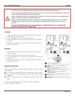
120 VAC
1.
Connect the white wire to both the neutral side of the line and the
common lead going to the motor.
2.
Connect the blue wire to the other side of the motor.
3.
Connect the black wire to the line side of the power line coming into
the control.
4.
Ensure the red wire has a marrette or similar connector installed to
insulate any bare wire.
230 VAC
1.
Connect the red wire to one side of the line and the common lead
going to the motor.
2.
Connect the blue wire to the other wire from the motor.
3.
Connect the black wire to the line side of the power line coming into
the control.
4.
Ensure the white wire has a wire nut or similar connector installed to
insulate any bare wire.
Temperature probe
Follow the guidelines below and connect the temperature probe as shown
in the diagram.
Do not run the probe cable in the same conduit as AC power cables
Do not run the sensor cable beside AC power cables or near electrical
equipment.
When crossing other cables or power lines, cross them at a 90 degree
angle.
You can extend probe cables up to 500 feet. For more information,
contact your dealer or Phason.
103413.01
Use liquid-tight connectors at the cable entry points and seal with
an RTV silicone.
120
VAC
230
VAC
Service
Panel
Enclosure
C C
Service
Panel
E
D
B
A
Whi
te
Red Blue
Black
Probe
Insulate
using a
#31 wire
nut or
similar
connector.
B
A
Prob
e
Insulate
using a
#31 wire
nut or
similar
connector.
Line
Neutral
Load
Fan
Fan
Load
Line
Line
A
Fuse: 15 A, 250 VAC ABC-type ceramic
B
Important:
A suitable switch must be installed between the control
and the motor.
Important:
Il est essentiel ou'un interrupteur convenable soit
installé entre le contröle et le moteur.
C
Caution:
For controlling shaded-pole, permanent-split-capacitor, or
universal motors only.
Caution:
Destiné uniouement à bague de déphasage ou à
condensateur permanent.
D
Connect all ground wires to the grounding terminal located near the
cable entry points.
E
Whi
te
Red Blue
Black


