PFT 00 28 08 02 Скачать руководство пользователя страница 27


PFT ZP 3 L MULTIMIX Overview – Operation – Spare Parts Lists 

Checking the direction of rotation of the ZP 3 L 


2016-07-04


27 


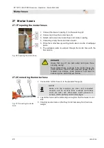
26.1  Checking the direction of rotation of the R7-3S 


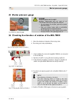
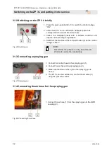
Fig. 32: Checking the direction of rotation 

1.  The pump unit 2L6 rotates to the right when viewed from the 

mortal pressure gauge. 


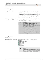
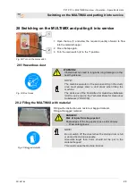
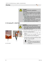
26.2 Switching on the ZP 3 L 


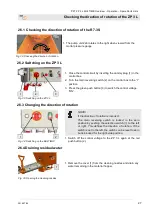
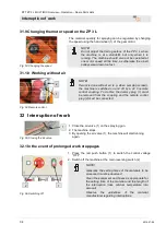
Fig. 33: Switching on the ZP 3 L 

1.  Close the control circuit by inserting the dummy plug (1) in the 

control box. 

2.  Turn the main reversing switch (2) on the control box to the “I” 

position. 

3.  Press the green push button (3) to switch the control voltage 

“ON”. 


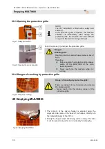
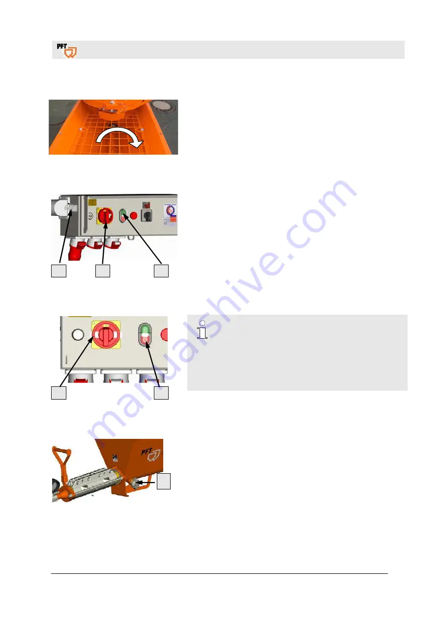
26.3 Changing the direction of rotation 


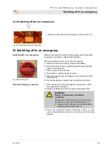
Fig. 34: Switching on the MULTIMIX 


NOTE! 

If the direction of rotation is incorrect: 

The  main  reversing  switch  is  locked  in  the  zero 
position by pushing the selection switch (1) to the left 
or  right.  This  defines  the  direction  of  rotation.  If  the 
switch is set to the left, the switch can be reset to zero 
but is blocked for the right-side position.  

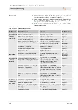
1.  Switch  off  the  control  voltage  to  the  ZP  3  L  again  at  the  red 

push button (2). 


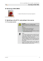
26.4 Draining residual water 


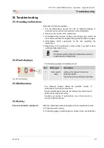
Fig. 35: Opening the cleaning nozzles 

1.  Remove the cover (1) from the cleaning nozzles and drain any 

water remaining in the material hopper. 


Содержание 00 28 08 02

Страница 1: ...Item number of operating manual 00 41 53 52 Item number of the machine 00 45 13 21 Item number of the machine 00 43 23 95 Item number of the machine 00 45 13 65 Item number of the machine 00 28 08 02...

Страница 2: ...7 04 Knauf PFT GmbH Co KG Postfach 60 97343 Iphofen Einersheimer Stra e 53 97346 Iphofen Germany Tel 49 0 93 23 31 760 Fax 49 0 0 93 23 31 770 Technical hotline 49 9323 31 1818 info pft iphofen de www...

Страница 3: ...2L6 ZP 3 L 14 10 4 Pump unit R7 3S 14 10 5 VARIO gear motor 5 5 kW item number 00280460 14 10 6 Control box ZP 3 L item number 00280800 15 11 Accessories 15 12 Recommended accessories 16 13 Intended...

Страница 4: ...1 10 Working without air 34 32 Interruption of work 34 32 1 In the event of prolonged work stoppages 34 32 2 Switching off the air compressor 35 33 Switching off in an emergency 35 34 Measures to be t...

Страница 5: ...shaft 56 42 6 Spare parts list Pump unit 2L6 57 42 7 Pump unit 2L6 with pump shaft Render Star 58 42 8 Spare parts list Pump unit 2L6 Render Star 59 42 9 Pump unit R7 3S 60 42 10 Spare parts list Pum...

Страница 6: ...0 14 EG Interne Fertigungskontrolle nach Artikel 14 Absatz 2 in Verbindung mit Anhang V Diese Erkl rung bezieht sich nur auf die Maschine in dem Zustand in dem sie in Verkehr gebracht wurde Vom Endnut...

Страница 7: ...ctiveness of the control and safety devices as well as the proper fitting of the protection devices The safe working condition of the machine has to be checked by the machine operator during operation...

Страница 8: ...include the operating manual when transferring the machine to third parties The diagrams and illustrations shown in the manual are intended for better understanding of tasks and descriptions They are...

Страница 9: ...y ZP 3 L 120 litres Container capacity ZP 3 L up to protective grille 80 litres Max mixing hopper MULTIMIX 140 litres Capacity for ready mixed product approx 80 litres Maximum particle size 6 mm 5 2 C...

Страница 10: ...ng period 8 hours 5 4 Output values Pump output 2L6 standard equipment Specification Value Unit Pump output approx 10 39 l min Max operating pressure 20 bar Granulation max 6 mm Pumping distance max f...

Страница 11: ...The type plate is found on the pump side material hopper and contains the following details Manufacturer Type Year built Machine number Permissible operating pressure 8 Quality control sticker Fig 4...

Страница 12: ...X 1 Material hopper ZP 3 L with frame 2 Protective grille ZP 3 L 3 Multimix material outlet 4 Multimix material hopper 5 Protective grille for MULTIMIX with bag opener 6 Water inlet 7 MULTIMIX limit s...

Страница 13: ...ug mains connection 7 Hand wheel Vario gearbox 8 Gear motor Vario 9 Wheel with steel rim 10 Cleaning nozzle 11 Pump unit 2L6 12 Mortar pressure gauge 13 Mortar hose connection 10 2 MULTIMIX for ZP3 L...

Страница 14: ...h handle 7 Coupling 35M part 8 Mortar pressure gauge 10 4 Pump unit R7 3S 1 2 3 4 5 6 7 8 Fig 9 Pump unit 1 Rotor R7 3S 2 Stator R7 3S 3 Clamp 4 Tie rods 5 Pressure flange 6 Push handle 7 Coupling 50M...

Страница 15: ...6A air compressor 10 CEE panel mounted socket 5 x 16A MULTIMIX WARNING Danger to life from rotating parts Improper operation may lead to serious damage to persons or property The motor must be operate...

Страница 16: ...ompressor is intended exclusively for the generation of compressed air and is to be used with connected implement Any other use or use beyond what is specified such as with freely accessible and or op...

Страница 17: ...compressor complies with the national and international safety regulations and can therefore also be used in damp rooms and or outdoors Areas with clean and dry air should be preferred Ensure that th...

Страница 18: ...pumps the mixed material directly to the application site The pumping capacity can be adapted to the material requirements The PFT ZP 3 L MULTIMIX can be switched on and off using a remote control 16...

Страница 19: ...ctive unit together with the machine Failure to follow these recommendations will result not only in the voiding of the warranty but the quality of the mortar you are producing will also suffer 18 Mor...

Страница 20: ...suspension points provided Only remove packaging shortly before assembly Suspended loads WARNING Danger of death due to suspended loads Falling or swinging parts can pose a fatal hazard when heavy loa...

Страница 21: ...ransport observe the following requirements The crane and lifting equipment must be suitable for the package weight The operator must be authorised to operate the crane Fastening the lifting gear 1 At...

Страница 22: ...separate the materials according to type and size and reuse or recycle them accordingly CAUTION Environmental damage can result from improper disposal of materials Packaging materials are valuable res...

Страница 23: ...y Components and tools that are stacked on one another or left lying around can cause accidents An increased noise level can cause permanent hearing loss Operation can result in noise that exceeds 95...

Страница 24: ...th due to electric current The electrical connection must be fused correctly Only connect the machine to a power source with an approved FI circuit breaker 30 mA RCD residual current device of type A...

Страница 25: ...f the mixing arms 2 The mixing unit runs anticlockwise 1 2 Fig 26 ZP 3 L Switching on 1 Check whether the connector plug MULTIMIX 1 is connected to the control box 2 Switch on the ZP 3 L using the mai...

Страница 26: ...0 Item number 00 13 02 05 Float switch for AV3000 Item number 00 13 09 32 NOTE When working with water from the barrel the inlet strainer must be fitted with a filter screen item no 00136619 Bleed the...

Страница 27: ...I position 3 Press the green push button 3 to switch the control voltage ON 26 3 Changing the direction of rotation 1 2 Fig 34 Switching on the MULTIMIX NOTE If the direction of rotation is incorrect...

Страница 28: ...t tear off can lash wildly and injure those standing nearby Never detach hose couplings if the mortar hoses are under pressure check mortar pressure gauge Mixed material can escape under pressure and...

Страница 29: ...hine operator or the person working in the dusty area must always wear a dust mask when filling the machine The decisions of the Committee for Hazardous Materials AGS can be read in the Technical Rule...

Страница 30: ...s a risk of injury Therefore Before opening the protective grille always switch off the MULTIMIX at the main reversing switch Never reach into the machine while it is running 28 4 Danger of crushing b...

Страница 31: ...k into the spraying gun Always wear protective goggles Always position the machine so that you cannot be hit should mortar escape NOTE The maximum pumping distance depends primarily on the flow charac...

Страница 32: ...regulations 4 Switch off the machine at the red push button 2 so the control voltage is OFF NOTE Never allow the pump to run dry since this will shorten its service life considerably 31 3 Connecting...

Страница 33: ...artially adhere to the sides of the material hopper resulting in the formation of tunnels The mortar level in the material hopper should not be higher than absolutely necessary 31 7 Switching on the Z...

Страница 34: ...and off by a 42 V remote control coupling To do this the dummy plug 1 must be removed from the coupling and the remote control plug 2 must be connected 32 Interruption of work Fig 55 Closing the air...

Страница 35: ...h against being activated again using a padlock 3 Inform supervisors at the site 4 If necessary call emergency services 5 Remove persons from the danger zone and carry out first aid measures 6 Ensure...

Страница 36: ...ed manner and injure the operator Only open the machine if the pressure has fallen to 0 bar DANGER Danger of injury due to leaking mortar Escaping mortar can lead to injuries to the eyes and face Ther...

Страница 37: ...pecialists do so NOTE A table below lists particular malfunctions and who is authorised to handle them 35 2 Fault displays The following equipment indicates a fault Fig 60 Fault displays Pos LED signa...

Страница 38: ...Contactor is defective Replace the contactor Service Control plug not connected Plug in control plug Operator Fuse is defective Replace the fuse Service Limit switch on protective grille Close the pr...

Страница 39: ...e connection cable Service technician Rotor worn or faulty Replace the rotor Service technician Stator worn or clamped too loosely Tighten the clamp or replace the stator Service technician Part not o...

Страница 40: ...ies In accordance with the accident prevention regulations of the Builder s Guild all personnel clearing blockages should wear personal safety equipment safety goggles protective gloves and position t...

Страница 41: ...mortar hoses if the pressure has fallen to 0 bar 36 3 Detaching coupling connections Fig 64 Hose blockages 1 Cover coupling connections with tear resistant film 2 Undo both nuts 1 on the pressure fla...

Страница 42: ...ly reattached when work is finished 37 2 Cleaning ZP 3 L MULTIMIX CAUTION Water can enter sensitive machine parts Before cleaning the machine seal all openings where water could enter and impair the s...

Страница 43: ...ortar pressure gauge 1 to see if the pressure has fallen to 0 bar DANGER Overpressure on the machine When opening machine components these can fly open in an uncontrolled manner and injure the operato...

Страница 44: ...merges at the end of the spray gun 6 Repeat this procedure if heavily soiled 7 For different hose diameters the mortar hoses should be cleaned separately with the appropriate sponge balls 38 Cleaning...

Страница 45: ...be retightened 2 Do not retighten the pump during operation 3 Pump components that are unable to produce the required feed pressure must be replaced When tightening or changing the pump ensure the fol...

Страница 46: ...injuries or equipment damage Ensure there is adequate space for assembly before starting any work Keep the assembly area clean and tidy Unattached components or tools left lying around or stacked on...

Страница 47: ...n again 40 2 MULTIMIX Maintenance tasks Provided no increase wear can be identified during regular inspections reduce the required maintenance intervals as appropriate for the actual signs of wear For...

Страница 48: ...Maintenance plan The next sections describe the maintenance tasks required for optimal problem free operation Provided no increased wear can be seen during regular inspections reduce the required main...

Страница 49: ...it out 4 Replace the filter if dirt is severe 5 Insert the filter with the rigid side of the filter 2 facing inwards Filter insert D 100 item number 20134000 Fig 82 Filter cover opening 6 Unscrew the...

Страница 50: ...an environmentally sound manner after reaching the end of its useful life 41 1 Safety Personnel Disassembly may only be performed by specially trained personnel Work on electrical systems may only be...

Страница 51: ...n again Disconnect the entire energy supply from the unit and discharge the residual energy Remove operating and auxiliary materials as well as residual processing materials and dispose of them in an...

Страница 52: ...IMIX Overview Operation Spare Parts Lists Spare parts drawing spare parts lists 52 2016 07 04 42 Spare parts drawing spare parts lists 42 1 Frame and protective grille ZP 3 L 1 2 3 4 2 5 12 11 10 16 1...

Страница 53: ...ctive grille ZP 3 L without cut out cpl 5 1 00 45 13 21 Protective grille ZP 3 L without cut out RAL2004 6 4 00 02 26 01 Round head screw M6 x 20 zinc plated 7 1 00 45 13 29 Cover plate drive ZP 3 L R...

Страница 54: ...PFT ZP 3 L MULTIMIX Overview Operation Spare Parts Lists Spare parts drawing spare parts lists 54 2016 07 04 42 3 Gear motor and sealing unit 1 2 15 14 13 12 11 10 9 8 7 6 5 4 3...

Страница 55: ...plated 5 1 00 10 41 38 Clamping flange without lubrication groove ZP 3 XXL RAL2004 6 1 00 40 49 55 Gasket without grease hole D180 d90 7 1 00 10 41 30 Clamping flange with lubrication groove ZP 3 RAL2...

Страница 56: ...ZP 3 L MULTIMIX Overview Operation Spare Parts Lists Spare parts drawing spare parts lists 56 2016 07 04 42 5 Pump unit 2L6 with pump shaft 1 2 3 4 5 6 7 8 9 10 11 12 13 14 24 23 22 21 20 19 9 18 17 1...

Страница 57: ...inc plated 10 1 00 10 22 29 Mortar pressure gauge 50 mm galv cpl 11 1 00 09 90 88 Pressure gauge with plastic housing 0 100 bar 1 2 pressure transmitter VA 12 1 00 09 94 51 Coupling for gauge 2 int ex...

Страница 58: ...FT ZP 3 L MULTIMIX Overview Operation Spare Parts Lists Spare parts drawing spare parts lists 58 2016 07 04 42 7 Pump unit 2L6 with pump shaft Render Star 1 2 18 17 16 15 14 13 12 11 3 4 5 6 7 8 9 10...

Страница 59: ...0 20 99 21 Flanged nut M16 zinc plated 8 1 00 28 08 55 Tie rods M16 x 600 mm 1 set 2 pieces 9 1 20 20 96 01 Hex screw M10 x 45 zinc plated 10 1 00 40 66 03 Pressure flange ZP 3 L cross web 2L6 RAL2004...

Страница 60: ...PFT ZP 3 L MULTIMIX Overview Operation Spare Parts Lists Spare parts drawing spare parts lists 60 2016 07 04 42 9 Pump unit R7 3S 1 2 3 4 5 6 7 8 9 10 18 7 17 16 15 14 13 2 12 11...

Страница 61: ...12 20 20 90 00 Washer B 13 zinc plated 8 1 00 28 08 55 Tie rods M16 x 600 mm 1 set 2 pieces 9 1 00 47 82 12 Assambling aid R pump RAL2004 10 1 00 09 90 89 Pressure gauge with plastic housing 0 100 ba...

Страница 62: ...erview Operation Spare Parts Lists Spare parts drawing spare parts lists 62 2016 07 04 42 11 MULTIMIX material hopper 1 2 3 4 5 26 25 24 23 22 21 20 19 18 17 16 37 36 35 34 33 32 31 30 29 28 27 6 2 7...

Страница 63: ...t D 4 5 with ring 15 1 00 28 42 98 Mortar outlet canted ZP 3 L RAL9002 16 1 00 00 79 86 Pin MULTIMIX outlet zinc plated 17 4 20 20 93 19 Washer 13 x 37 x 3 zinc plated 18 4 20 20 89 00 Safety nut M12...

Страница 64: ...FT ZP 3 L MULTIMIX Overview Operation Spare Parts Lists Spare parts drawing spare parts lists 64 2016 07 04 42 13 Mixing unit with gear motor 1 2 3 4 5 6 7 8 9 10 11 12 13 14 19 18 17 23 22 21 20 15 1...

Страница 65: ...asher B 13 zinc plated 8 6 20 20 91 10 Spring washer B 12 zinc plated 9 6 20 20 99 62 Screw M12 x 35 zinc plated 10 1 00 28 47 16 Mixing arm inside MULTIMIX RAL9002 11 1 00 28 47 35 Mixing arm outside...

Страница 66: ...PFT ZP 3 L MULTIMIX Overview Operation Spare Parts Lists Spare parts drawing spare parts lists 66 2016 07 04 42 15 Air compressor Item no 00414337 1 2 3 4 5 6 7 8 7 9 8 10 7 11 14 13 12 8 17 16 15...

Страница 67: ...4 int thread galv 7 3 20 20 36 50 Angle 1 4 int thread ext thread galv 8 3 20 20 37 12 Screwed joint 1 4 ext thread brass for pressure switch 9 1 20 21 90 51 Double counter flow valve 1 4 int thread...

Страница 68: ...PFT ZP 3 L MULTIMIX Overview Operation Spare Parts Lists Spare parts drawing spare parts lists 68 2016 07 04 42 17 Pressure switch off 1 2 3 4 5 6 7 8 9 10 11 18 6 17 16 15 14 13 12...

Страница 69: ...ead non blocking 6 2 00 05 91 96 Hose clamp 19 21 7 1 20 19 04 11 Hose screw joint 1 4 ext thread socket 1 2 8 1 20 20 45 70 T piece 1 4 int thread galv 9 1 20 20 36 50 Angle 1 4 int thread ext thread...

Страница 70: ...2 1 20 19 61 00 Spray head 35 mm 3 1 20 20 99 80 Ring bolt M10 x 19 zinc plated 4 1 20 19 01 00 Air nozzle tube 140 mm 5 1 20 19 05 10 Hose section 9 mm x 310 mm 6 2 20 20 261 1 Hose clip 14 17 7 1 2...

Страница 71: ...3 L RAL 9002 structure 5 1 00036249 Lock for switching box double bit key 6 1 00206458 Main reversing switch 4 pin 7 1 00053832 Light switch On Off twin button 8 1 00053831 Membrane rectangular for tw...

Страница 72: ...A PKZM0 10 5 1 00042602 Motor protection switch 10 16A PKZM 0 16 6 1 00021401 Auxiliary contact NHI 11 PKZO 7 2 00084224 Air break contactor DIL M15 10 42 V 8 1 00206458 Main reversing switch 4 pin 9...

Страница 73: ...PFT ZP 3 L MULTIMIX Overview Operation Spare Parts Lists Spare parts drawing spare parts lists 2016 07 04 73 42 21 Circuit diagram S1211...

Страница 74: ...PFT ZP 3 L MULTIMIX Overview Operation Spare Parts Lists Spare parts drawing spare parts lists 74 2016 07 04...

Страница 75: ...ling with malfunctions 37 Description 18 Design and function 12 Detaching coupling connections 41 Dimension sheet ZP 3 L MULTIMIX 11 Disassembly 51 Disassembly 50 Discharging mortar pressure 36 Dispos...

Страница 76: ...tective equipment Installation 37 Protective equipment for operators 22 Pump unit 2L6 56 Pump unit 2L6 with pump shaft Render Star 58 Pump unit 2L6 ZP 3 L 14 Pump unit R7 3S 14 Pump unit R7 3S 60 R Re...

Страница 77: ...L and putting it into service 31 Switching on the ZP 3 L briefly 32 T Table of malfunctions 38 Technical data ZP 3 L MULTIMIX 9 Transport 20 21 Transport by crane 21 Transport checklist 21 Troublesho...

Страница 78: ...PFT ZP 3 L MULTIMIX Overview Operation Spare Parts Lists 78 2016 07 04...

Страница 79: ...PFT ZP 3 L MULTIMIX Overview Operation Spare Parts Lists 2016 07 04 79...

Страница 80: ...Parts Lists 80 2016 07 04 THE FLOW OF PRODUCTIVITY Knauf PFT GmbH Co KG Postfach 60 97343 Iphofen Einersheimer Stra e 53 97346 Iphofen Germany Tel 49 9323 31 760 Fax 49 9323 31 770 Technical hotline 4...

Отзывы: