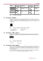
Pins
Switching
function
Description
Switching
function
Description
12
Error or device switched
off
No errors
3
11
Tbl. 1:
Switching functions
1.4 "RS-485" connection
The "RS-485" connection enables control of the device using a computer or terminal. The use of a Y-
distributor permits the integration into a bus system. You can connect the serial interface with a shielded
cable (EMC compatibility) to the "RS-485" connection on the rear of the device.
4
1
3
2
5
Fig. 4:
"RS-485" connection (5-pole Binder M12 socket)
1 RS-485+ (differential)
2 +24 V (DC), ≤ 200 mA
4
RS-485
-
(differential)
5
unassigned
3 Ground (GND)
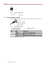
1.5 "USB" connection (type A)
The "USB" connection (type A) with master functionality is located on the front side and is used to con-
nect a USB memory stick (e.g. firmware updates, storing parameters (reading/writing), data logger).
1
4
Fig. 5:
"USB" connection (type A)
1 VBUS (5 V)
3
D+
2 D-
4
Earth (GND)
1.6 "USB" connection (type B)
The "USB" connection (type B) enables direct communication with the device via a computer (e.g. firm-
ware updates, storing parameters (reading/writing)). You can connect the USB interface with a
screened cable (EMC compatibility) to the connection on the rear side of the device.
If a virtual series interface (COM) is not automatically set up, you can download the driver from
Chip (Virtual COM Port Drivers)
1
4
2
3
Fig. 6:
"USB" connection (type B)
1 VBUS (5 V)
3
D+
2 D-
4
Ground (GND)
Interfaces
Содержание PT G28 500
Страница 99: ......
Страница 100: ... BG6007 ed A Date 1910 P N BG6007Bxx ...


