Adjustment
17
1
.05.10
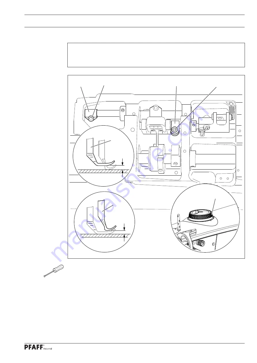
Top feed stroke
Requirement
With adjustment wheel
1
set at "
5
", the top feed dog
7
and presser foot
4
should each
rise by
5
.
0
mm
.
●
Remove the bottom feed dog and set adjustment wheel
1
at "
5
".
●
Loosen the screws of the needle plate, place the metal gauge over the opening of the
needle plate slot so that both sewing feet can be lowered onto the metal gauge.
●
For the preliminary adjustment, adjust crank
2
(screw
3
) so that there is a clearance of
5
mm
between presser foot
4
and the needle plate.
●
Adjust crank
5
(screw
6
) so that top feed dog
7
and presser foot
4
have the same stroke.
●
Check the adjustment in accordance with the
requirement
, and correct if necessary.
Fig. 1 - 10
7
5 mm
4
5 mm
2
3
5
6
1
Содержание Powerline 2545
Страница 47: ...47 Circuit diagrams Version 27 07 07 91 191 523 95 Part 1 ...
Страница 48: ...48 91 191 523 95 Part 2 Version 27 07 07 Circuit diagrams ...
Страница 51: ...51 Circuit diagrams Version 10 08 10 91 191 519 95 Part 1 ...
Страница 52: ...52 91 191 519 95 Part 2 Version 20 04 12 Circuit diagrams ...
Страница 53: ...53 Circuit diagrams Version 20 04 12 91 191 519 95 Part 3 ...
Страница 54: ...54 91 191 519 95 Part 4 Version 20 04 12 Circuit diagrams ...


