Adjustment
11
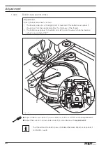
Activate lifting movement
●
Lifting movement is activated if connection part
8
is swiveled in as shon in
fi gures
1
-
05
a, and screws
9
(M
6
x
16
) and
10
(M
5
x
1
6) have been attached.
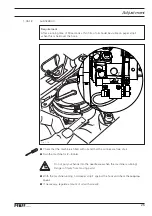
Deactivate lifting movement
●
Remove screws
9
and
10
and swivel connection part
8
(screw
11
) towards the right.
●
Replace screw
9
with a screw M
6
x
25
.
●
Replace screw
10
with a threaded pin M
5
x
25
and tighten to stop.
Adjust transporter height with deactivated stroke movement so that the upper
edge of the transporte is at the height of the upper edge of the needle plate.
Adjust the transporter height once again with the stroke movement activated,
as described in chapter
1
.
05
.
0
6.
Fig. 1 - 05a
10
9
8
11
8
Содержание Powerline 2545
Страница 47: ...47 Circuit diagrams Version 27 07 07 91 191 523 95 Part 1 ...
Страница 48: ...48 91 191 523 95 Part 2 Version 27 07 07 Circuit diagrams ...
Страница 51: ...51 Circuit diagrams Version 10 08 10 91 191 519 95 Part 1 ...
Страница 52: ...52 91 191 519 95 Part 2 Version 20 04 12 Circuit diagrams ...
Страница 53: ...53 Circuit diagrams Version 20 04 12 91 191 519 95 Part 3 ...
Страница 54: ...54 91 191 519 95 Part 4 Version 20 04 12 Circuit diagrams ...


