Adjustment
14 - 19
14
.17
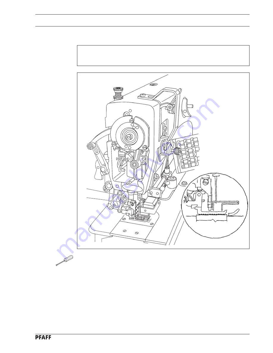
Position of the vibrating presser
Requirement
With the bottom feed dog at its top point of reversal the vibrating presser must be parallel
to the bottom feed dog.
●
Turn eccentric pin
1
(screw
2
) in accordance with the
requirement
.
2
1
Fig. 14 - 17


