Pfaff 3822-2/42 Скачать руководство пользователя страница 111

Adjustment

13 - 43

 49-106

49-109

49-108

49-107

1

2

5

4

3

1

Fig.13 - 41

13

.06.12

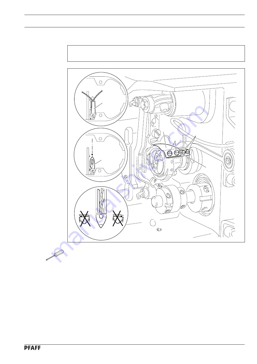
Manual trimming control

Requirement

Both threads have to be cut perfectly in the catcher cutout on both right and left-hand side.

Position the needle bar at b.d.c and activate the engaging lever manually.

Turn the hand wheel until thread catcher 

1

 is its front reversal point.

Double a thread and insert it into the cutout of thread catcher 

1

.

Turn the hand wheel further until the trimming process is finished.

If both threads are not trimmed in accordance with the 

requirement,

 loosen screws 

2

and align thread catcher 

1

 with respect to knife 

.

Make sure that the tip of the thread catcher is pointing to the centre of the needle and

tighten screws 

firmly.

Move catcher stop 

4

 onto thread catcher 

1

 and tighten screws 

5

 firmly.

Screw on feed dog and needle plate, making sure that the movement of the feed dog in

the needle plate cutout is not restricted.

Содержание 3822-2/42

Страница 1: ...Instruction Manual 296 12 18 592 002 Betriebsanleitung engl 01 06 3822 This instruction manual applies to machines from the following serial numbers onwards 2719930 2 42 2 44...

Страница 2: ...s Reprinting copying or translation of PFAFF instruction manuals whether in whole or in part is not permitted without our prior permission and not without written indication of the source PFAFF Indust...

Страница 3: ...es 5 1 5 03 Disposal of packing materials 5 1 5 04 Storage 5 1 6 Explanation of symbols 6 1 7 Controls 7 1 7 01 Main switch 7 1 7 02 Pedal 7 1 7 03 Presser bar lifter 7 2 7 04 Knee Switch 7 2 7 05 Lef...

Страница 4: ...11 01 02 Seam program input with the Creating adjusting a program function 11 4 11 01 03 Entering the actual and required length of the seam section 11 6 11 01 04 Seam program input with the Creating...

Страница 5: ...n 13 19 13 05 18 Basic setting of the differential adjustment device 13 20 13 05 19 Eccentric hook shaft bearing and hook to needle clearance 13 21 13 05 20 Needle bar rise readjustment of the needle...

Страница 6: ...ack knife in relation to the hook knife 13 56 13 08 07 Cutting angle of the back knife in relation to the hook knife 13 57 13 08 08 Cutting pressure between the back knife and the hook knife 13 58 13...

Страница 7: ...ed without its safety devices all regulations relevant to safety must be adhered to When part sets are changed e g needle presser foot needle plate feed dog or bob bin during threading when the workpl...

Страница 8: ...on manual belongs to the equipment of the machine and must be available to the operating staff at all times This instruction manual must be read before the machine is operated for the first time Both...

Страница 9: ...02 Technical staff Technical staff are persons who have been trained in electrical engineering electronics pneumatics and mechanical engineering They are responsible for lubricating servicing repairi...

Страница 10: ...pped or slung out of the mach ine Do not operate the machine without take up lever guard 1 Danger of injury by movement of take up lever Do not operate the machine without finger guard 2 Danger of inj...

Страница 11: ...ol panel PFAFF 3822 2 44 Edge trimmer for feathered trimming and touch screen control panel Any use of these machines which is not approved by the manufacturer shall be considered as improper use The...

Страница 12: ...alternating voltage Max power 400 VA Fuse protection 1 x 16 A inert Working air pressure 6 bar Air consumption on the Pfaff 3801 3 07 and the PFAFF 3801 3 071 40 l work cycle Noise data Emission sound...

Страница 13: ...d various plastic mat erials The electrical equipment comprises plastic materials and copper The machine is to be disposed of according to the locally valid pollution control regula tions if necessary...

Страница 14: ...he machines are only transported in an upright position 5 03 Disposal of packing materials The packing materials of this machine comprise paper cardboard and VCE fibre Proper dis posal of the packing...

Страница 15: ...struction manual work to be carried out or important information is accentuated by symbols These symbols have the following meanings Note information Cleaning care Lubrication Maintenance repairs adju...

Страница 16: ...7 02 Pedal 0 Neutral position 1 Lower presser foot 2 Sewing 1 Raise presser foot 2 Trim threads Fig 7 02 0 1 2 1 2 Fig 7 01 7 Controls 7 01 Main switch The machine is switched on or off by turning mai...

Страница 17: ...rning lever 1 Fig 7 03 1 7 04 Knee Switch Manual sewing By operating knee switch 1 it is possible to alternate between two pre set amounts of fullness Programmed sewing By operating knee switch 1 the...

Страница 18: ...epending on the operating condition of the machine different symbols and or texts are displayed If the symbols or texts are framed these show functions which can be selected by pressing the appropriat...

Страница 19: ...y pressing a key same function as left knee switch Bartack inversion Programmed bartacks can be suppressed by pressing a key Number keys 0 12 The previously allocated amount of fullness is called up b...

Страница 20: ...rdy including during all sewing operations 8 01 Mounting The necessary supply connections for the electrical and pneumatic systems must be available at the machine s location see Chapter 3 Specificati...

Страница 21: ...of V belt guard 1 with screws 2 Fasten top section of V belt guard 3 with screws 4 Attach belt guard sections 1 and 3 with screws 5 Fig 8 03 3 4 1 2 2 4 5 5 109 020 8 01 02 Tightening the V belt Fit...

Страница 22: ...at stop 1 is in the slot of synchronizer 3 see arrow Tighten screws 4 just a little Insert the plug for the synchronizer in the socket on the control box Adjust synchronizer 3 see Chapter 13 05 01 Bas...

Страница 23: ...ons and earth cables Connect all plugs as labelled in the control box 1 Screw the earth cable from the sewing head to earth point A Connect earth point C and earth point A with an earth cable Screw th...

Страница 24: ...nting and commissioning the machine 8 01 07 Fitting the reel stand Fit the reel stand as shown in Fig 8 07 Afterwards insert the stand in the hole in the table top and secure it with nuts pro vided Fi...

Страница 25: ...ny irregularities do not operate the machine under any circumstances The machine may only be connected to a grounded socket When the machine is running the balance wheel must turn towards the operator...

Страница 26: ...rated from the electricity supply by removing the plug from the mains or switching off the On Off switch 9 01 Inserting the needle Switch off the machine Danger of injury by unintentional starting of...

Страница 27: ...it a few times around bobbin 1 in a clockwise direction Switch the bobbin winder on by pushing the bobbin winder spindle 2 and lever 3 simultaneously The bobbin is wound during sewing The tension of...

Страница 28: ...case 2 Inserting the bobbin case Insert bobbin case 1 until you feel it click into place Fig 09 03 1 2 9 04 Threading the bobbin case adjusting the thread tension Insert bobbin 1 into bobbin case 2 Gu...

Страница 29: ...reading the needle thread Switch off the machine Danger of injury if the machine is started accidentally Thread the needle thread in accordance with Fig 09 05 9 06 Adjusting the needle thread tension...

Страница 30: ...nput menu Select the desired program number Confirm the selection and quit the selection menu The sewing method is determined by the program number selected see Chapter 10 Sewing Program number 0 Manu...

Страница 31: ...menu Select program number 0 Confirm the selection and quit the selection menu Enter the desired value with the appropriate arrow keys If necessary allocate the current fullness amount to one of the n...

Страница 32: ...ion 9 09 Entering altering the code number Switch on the machine Call up the input mode Select parameter 800 Select the code number input menu Enter the code number on the number keys factory code set...

Страница 33: ...nclude input Do not forget the code Without the appropriate code the protected functions cannot be called up Help is then only possible through PFAFF service staff The code input remains stored until...

Страница 34: ...l Switch on the machine Call up the input mode Select the service menu Select control panel functions Change the display contrast Switch the key tone off or on Never reduce the display contrast to the...

Страница 35: ...sition are shown on the display when sewing starts and like the functions at the beginning and end of the seam the material type and the needle and sewing foot positions can be changed directly with t...

Страница 36: ...d the needle moves to its highest position after sewing stops Thread trimming when the function is activated enables thread trimming with the pedal function optional when the function is activated the...

Страница 37: ...ch on the single start backtack function and call up the menu for entering the values or Switch on the double start backtack function and call up the menu for entering the values In each case change t...

Страница 38: ...n sewing different materials in the manual sewing mode and when working with fixed programs it is possible to choose between 3 different types of material at any time Light materials Medium materials...

Страница 39: ...sections and can be changed at any time with the corresponding function Switch on the machine and select program number 1 or 2 see Chapter 9 07 Selecting the program number Explanation of the display...

Страница 40: ...trimming with the pedal function optional when the function is activated the edge knife can be switched off with the pedal function see Chapter 7 02 Pedal Sewing foot raised When this function is act...

Страница 41: ...the current seam section the corresponding parameters for seam section number fullness with fullness adjustment and the number of stitches length of seam section are displayed The material typ and ot...

Страница 42: ...ogram sequence see Chapter 10 03 01 Program interruption Thread trimming when the function is activated enables thread trimming with the pedal function optional when the function is activated the edge...

Страница 43: ...s and carry out the other functions as in manual sewing see Chapter 10 01 Manual sewing If necessary call up programmed sewing again 10 04 Error messages If an error occurs the text ERROR appears on t...

Страница 44: ...alue Change the value of the selected parameter see Chapter 13 09 02 Example of a parameter input Software information Calls up information about the current machine software Creating adjusting a prog...

Страница 45: ...o select the program number and the basic settings of the seam program which is to be sewn 11 01 01 Basic settings for seam program input The basic settings in the creating adjusting a program and the...

Страница 46: ...h right seam only Sewing program with left and right seam beginning with the left seam Conclude the input of the basic settings and change to the seam section input see Chapter 11 01 02 Seam program i...

Страница 47: ...Entering the actual and the required length of the seam section Alter the fullness see Chapter 9 08 Inputting fullness Alter the maximum speed for the current seam section These functions are used to...

Страница 48: ...nclude the input of the current seam and store the parameter for the other seam in the reverse order mirror seam Set the seam end or program end If entering only one seam only the right or only the le...

Страница 49: ...er of stitches and the fullness amount are calculated A subsequent alteration of the fullness amount or the number of stitches also alters the values for the actual and required length First of all it...

Страница 50: ...owing displays and functions appear on the screen 1 Enter the functions for the seam start see Chapter 10 01 01 Entering the seam start and seam end in the manual sewing mode Enter the fullness see Ch...

Страница 51: ...nd of seam section input during seam programming Condensed stitches defined during the input of the functions for the end of the seam section will be carried out after the seam program input has been...

Страница 52: ...call up the menu for entering the values or Switch on the single start backtack function and call up the menu for entering the values or Switch on the double start backtack function and call up the me...

Страница 53: ...hange the number of stitches for the condensed stitches or the number of backtack stitches with the appropriate arrow keys Change the value for the maximum speed during the condensed stitches or backt...

Страница 54: ...Input 11 11 Conclude the input and change to programmed sewing It is not possible to set every combination of functions All the activated functions are shown as inverse symbols...

Страница 55: ...s and be stored under the program number 4 with the comment PROG Seam section 3 Actual length 103 Required length 95 Seam area 1 Number of stitches 40 Fullness 25 Seam area 4 Fullness 0 Without stitch...

Страница 56: ...ate symbol appears Call up the menu for comment input Enter the comment PROG with the keyboard and number panel Conclude the comment input Change to the input of the first seam section Enter the value...

Страница 57: ...up the menu for entering the functions at the end of the seam section Switch on the function for changing to the next seam section with the knee switch Conclude the input of the end of the seam secti...

Страница 58: ...nter the value 95 for the required length The number of stitches 37 and the value for the fullness 70 are calculated from the values entered As this calculation is based on whole stitches the value fo...

Страница 59: ...fullness Call up the menu for entering the functions at the end of the seam section Switch on the stitch count function to change to the next seam section and set value 40 for the number of stitches C...

Страница 60: ...Input 11 17 Activate the end of program function Conclude the seam program input and change to programmed sewing...

Страница 61: ...number 11 with the comment TEACH Seam area 3 Learn number of stitches Fullness 20 Seam area 1 Learn number of stitches Fullness 25 Seam area 4 Without stitch count End with knee switch Fullness 0 Seam...

Страница 62: ...pe only left seam by pressing until the appropriate symbol appears Call up the menu for comment input Enter the comment TEACH with the keyboard and number panel Conclude the comment input Change to th...

Страница 63: ...h on the function for changing to the next seam section by knee switch Conclude the input of the end of the seam section Use the pedal function to sew the second seam section Change to the input of th...

Страница 64: ...s Use the pedal function to sew the fifth seam section Set the end of the seam section with the right knee switch see Chapter 7 04 Right knee switch Change to the input of the sixth seam section Enter...

Страница 65: ...p the basic display for the input mode Sewing mode Quit input mode and call up sewing mode Program selection After the program administration has been selected at least one seam program is always mark...

Страница 66: ...ls are calculated for the average running time of a single shift operation If the machine is operated for longer periods shorter maintenance intervals are recommended 12 01 Cleaning the machine Switch...

Страница 67: ...1 Afterwards lubricate these points with the special lubricant part no 99 137 467 91 wipe off surplus lubricant with a cloth 49 10 49 025 12 02 Oil level of the machine Check the oil level once a mont...

Страница 68: ...o pull knob 2 upwards and turn it so that the gauge shows a pressure of 6 bar 12 05 Cleaning the air filter of the air filter lubricator Switch the machine off Disconnect the air hose at the air filte...

Страница 69: ...es which have to be completely adjusted If only specific individual work steps are carried out both the preceding and following chapters must be observed Screws nuts indicated in brackets are fastenin...

Страница 70: ...apply pressure Turn the balance wheel slightly backwards and forwards until the pin locks into the rear crank recess in this way blocking the machine Adjustment hole 1 0 6 mm past top dead centre of t...

Страница 71: ...e 13 05 01 Basic position of the machine Switch on the machine Call up the input mode By turning the balance wheel position the needle point flush to the stop edge of the needle plate Conclude the inp...

Страница 72: ...mm 13 05 02 Preliminary adjustment of the needle height Requirement With the needle bar at b d c the distance between bottom edge of the needle bar and the needle plate must be16 5 mm Adjust needle b...

Страница 73: ...e needle hole Loosen screws 1 2 and 3 Adjust the needle bar frame 4 both crosswise and in the direction of sewing according to the requirement and tighten screw 2 slightly and screw 3 With screw 1 dra...

Страница 74: ...ed dog when the balance wheel is turned Loosen screw 1 nut 2 Set stitch length at 0 Turn eccentric bush 3 screw 4 so that the marking is pointing downwards and the surface of eccentric bush 3 is at an...

Страница 75: ...t With the maximum stitch length set and the needle bar positioned 0 6 mm past t d c adjustment hole 1 the bottom feed dog should not move when the reverse feed key is operated Bring needle bar to 0 6...

Страница 76: ...Requirement 1 With the needle bar set 0 6 past t d c adjustment hole 1 and the stitch length set at 0 the bottom feed dog should be at the top of its stroke 2 The cutout of eccentric 1 should be more...

Страница 77: ...og should be in the centre of the needle plate cutout as seen from the side and in the direction of feed 2 The bottom feed dog should be at the top of its stroke and its entire length should be positi...

Страница 78: ...ser foot presser reduce pressure Push out bolt 1 screw 2 and remove connection element 3 from the yoke of lever 4 By turning the balance wheel bring lever 5 to its furthest point of reversal Place fee...

Страница 79: ...justment foot 1 part no 61 111 639 20 is resting on the needle plate stop 4 should be touching screw 2 2 2 2 2 Remove presser foot Attach adjustment foot 1 part no 61 111 639 20 and lower it onto the...

Страница 80: ...eely if necessary adjust lever 2 Align top feed dog in the centre of the presser foot cutout in the direction of sewing screw 5 Loosen screw 7 Align the hole of lever 8 with the elongated hole of leve...

Страница 81: ...0 and with the adjustment gauge 4 fitted there should be no feeding motion of the top feed dog The stitch length limitation screw 1 in Chapter 13 05 04 Neutral position of the bottom feed dog must be...

Страница 82: ...the needle bar is positioned 0 6 mm past t d c adjustment hole 1 and the maximum stitch length is set lever 3 should not move when the feed reverse key is operated While continuously operating the fe...

Страница 83: ...equirement With the needle bar positioned 0 6 past t d c adjustment hole 1 there must be a distance of approx 16 5 mm between the eye of the linkage rod 2 and machine case 3 Bring needle bar to 0 6 pa...

Страница 84: ...ate Lower the presser foot 1 onto the needle plate Set stitch length at 3 By turning the balance wheel bring top feed dog 2 to its t d c Turn eccentric pin 3 screw 4 so that its greatest eccentricity...

Страница 85: ...dog Requirement When the stitch length is set at 4 and with adjustment gauge 3 fitted the top feed dog should rest on the ascending bottom feed dog when this reaches the top edge of the needle plate...

Страница 86: ...h adjustment Requirement When set at 3 the stitch length must be the same size when sewing forwards or in reverse Loosen screw 2 Adjust bush 1 according to the requirement Take care that the eccentric...

Страница 87: ...hould be set so that the maximum stitch length is 2 7 mm 2 The top stroke of rocking bar 6 should be set so that the stitch length is 2 7 mm when the feed reverse key is pressed down as far as possibl...

Страница 88: ...erential adjustment device Requirement With the fullness set at 0 the stitch length at 2 7 and the adjustment gauge 5 fitted the roller 2 should be touching pressure sleeve 4 Switch on the machine Pre...

Страница 89: ...ly on the spinning disc 4 and the point of the hook is positioned towards the centre of the needle there must be a clearance of 0 05 0 1 mm between the point of the hook and the needle groove 3 Gear 5...

Страница 90: ...1 The point of the hook should be in centre of the needle and the top edge of the needle eye should be 0 8 mm below the hook point 2 There should be a clearance of 0 5 mm between the lug of position...

Страница 91: ...ener height Requirement When bobbin opener 3 is at its left point of reversal the top edge of its finger should be 0 5 mm above the bottom edge of the bobbin case cam Loosen screw 2 Adjust bobbin open...

Страница 92: ...5 must be 0 8 mm 2 When the bobbin opener 3 is at its left point of reversal the bobbin case base 5 should be deflected by approx 0 3 mm by the retaining finger and screw 1 should be resting on stop...

Страница 93: ...the needle bar is positioned 1 8 mm past b d c the bobbin opener 3 should be at its right point of reversal Loosen screws 2 Adjust bobbin opener eccentric 1 according to the requirement Tighten screws...

Страница 94: ...ead tension release Requirement When the hand lever 1 is raised the tension discs should be at least 0 5 mm apart Adjust tension release clip 2 screw 3 according to the requirement Lower the presser f...

Страница 95: ...he thread check spring 3 must be finished when the needle point enters the material spring path approx 7 mm Adjust thread tension 1 screws 2 according to the requirement The path of thread check sprin...

Страница 96: ...engaged friction wheel 3 must not rest on drive wheel 1 2 The bobbin winder should switch itself off when the thread is approx 1 mm from the edge of the bobbin Raise hand lever and switch on bobbin wi...

Страница 97: ...feed dog in relation to the sewing foot Requirement When the take up lever is at its t d c the teeth of the top feed dog should not be below the presser foot shoe when the presser foot is raised Adju...

Страница 98: ...8 1 2 ca 12 mm 13 05 28 Top feed dog and sewing foot pressure Requirement Even at top speed the material must be fed perfectly No pressure marks should appear on the material Adjust screws 1 and 2 acc...

Страница 99: ...sation Requirement When cylinder 3 is actuated the machine must sew with a shorter stitch length than that indicated on the stitch length adjuster Activate the stitch condensation and sew a test seam...

Страница 100: ...ide of the trip should be flush with the right hand side of pawl 8 Pull the ball heads of connecting rod 1 off the ball pin at the cutting and control units and remove connecting rod 1 Loosen screws 2...

Страница 101: ...e easily with the control cam 7 and 2 the roller of roller lever 4 should be centred in the cam notch of the control cam 7 Unscrew screws 1 and 2 Put pressure on rockshaft 3 3 3 3 3 to the right Adjus...

Страница 102: ...nt With the thread trimmer in resting position the distance between pawl 2 and the highest point of the control cam should be 0 3 mm Position the bearing surface of control cam 1 with its highest poin...

Страница 103: ...ging solenoid is actuated the distance between the engaging lever 1 and the pawl 2 should be between 0 2 and 0 3 mm Position the needle bar 1 8 mm after b d c Manipulate engaging lever 1 until pawl 2...

Страница 104: ...2 2 2 and the bottom of the control cam 3 must be approx 0 2 mm Position needle bar 1 8 mm after b d c Activate engaging lever 1 manually Push roller lever 2 onto the bottom of control cam 3 Tighten s...

Страница 105: ...the needle bar is at the t d c and the thread trimmer is in resting position the distance between the roller of the roller lever 3 and the outer diameter of the control cam 4 should be between 0 3 an...

Страница 106: ...the thread catcher carrier Adjust thread catcher 6 laterally in accordance with requirement 1 Tighten screws 5 firmly ensuring that the back of the thread catcher is horizontal Needle plate feed dog k...

Страница 107: ...m in front of the bobbin case position finger 4 Push balls of the connecting rod 1 onto the ball pins on the cutting and control units Loosen nuts 2 right hand and left hand thread Position needle bar...

Страница 108: ...on finger the distance between the tip of the thread catcher 6 and the middle of the lug should also be 2 mm Position the needle bar at b d c Activate the engaging lever manually Turn the hand wheel u...

Страница 109: ...er is in resting position the distance between the retaining spring 1 and the roller lever 3 3 3 3 3 should be 0 5 mm Position retaining spring 1 together with the cover disk Tighten screws 2 sligthly...

Страница 110: ...osition the needle bar at b d c Push knife 1 under the safety plate and align in accordance with the requirement Tighten screw 2 slightly Activate the engaging lever manually Turn the hand wheel until...

Страница 111: ...ad and insert it into the cutout of thread catcher 1 Turn the hand wheel further until the trimming process is finished If both threads are not trimmed in accordance with the requirement loosen screws...

Страница 112: ...elease cone 1 nut 2 in accordance with requirement 1 Lower the presser foot onto the needle plate Pull out the thread from between the tension disks Pull down linkage 3 screw 4 until you feel it stop...

Страница 113: ...osition the needle bar at b d c Place the thread trimming unit in position and slightly turn screws 4 Activate engaging lever 5 manually so that roller lever 6 engages with control cam 7 Adjust the th...

Страница 114: ...3822 2 42 13 07 01 Knife stroke Requirement When the needle bar is at its t d c adjustment hole 5 the knife must be at the top of its stroke Switch on the machine Switch on the edge trimming device B...

Страница 115: ...49 44 1 2 13 07 02 Neutral position of the knife stroke Requirement When the edge trimming device is switched off the top knife should not move when the balance wheel is turned Turn crank 1 screw 2 ac...

Страница 116: ...4 0 5 mm 13 07 03 Knife height Requirement When the knife 1 is in its lowest position the front edge of the knife blade should be approx 0 5 mm below the top edge of the needle plate Adjust knife 1 sc...

Страница 117: ...without the knife spur striking the stationary knife 3 The knife should stand slightly slanted to the stationary knife shear effect Adjust knife mounting 1 screw 2 according to requirement 1 Switch on...

Страница 118: ...lifting rod 1 as far as possible Adjust eccentric 2 screw 3 according to the requirement 13 07 05 Adjusting the stop eccentric Requirement When stop 4 is touching eccentric 2 there should be a distan...

Страница 119: ...of the knife Requirement The downward motion of the knife must begin when the descending needle eye is level with the needle plate Switch on the machine Set the maximum knife stroke Switch on the feat...

Страница 120: ...ngle of the front knife Requirement The knife 5 should 1 Touch the stationary knife without pressure and 2 Be at a 0 1 mm slant to the stationary knife Adjust knife mounting 1 screws 2 according to re...

Страница 121: ...3 51 1 2 3 0 8 mm 13 08 03 Cutting position of the front knife Requirement The rear edge of knife 3 must be positioned 0 8 mm in front of the needle plate cutout Adjust knife mounting 1 screw 2 accord...

Страница 122: ...sure of the front knife Requirement 1 Only as much cutting pressure as absolutely necessary should be applied 2 After the cutting pressure has been set the slant of the knife must not be less than 0 0...

Страница 123: ...ig 13 53 1 2 13 08 05 Knife stroke zero point Requirement When the feathered trimming device is switched off the top knives should not move when the balance wheel is turned Adjust crank 1 screw 2 acco...

Страница 124: ...49 056 1 2 49 071 3 1 13 08 06 Side position of the back knife in relation to the hook knife Requirement The back edge of the back knife 1 should be even with hook knife 3 Adjust knife 1 screws 2 acco...

Страница 125: ...1 should be at a 0 05 0 1 mm slant to the back knife 2 Switch the machine on and let it move into position Switch on the edge trimming and feathered trimming device Slide hook knife 1 into cutting po...

Страница 126: ...cessary should be applied 2 After the cutting pressure has been set the slant of the back knife must not be less than 0 05 mm If the cutting pressure is too high there is a risk of the hook knife brea...

Страница 127: ...itch the machine on and let it move into position Switch on the edge trimming and feathered trimming device keyboard Bring hook knife 1 into cutting position keyboard By turning the balance wheel brin...

Страница 128: ...quirement When the back knife 3 begins cutting the front knife 1 should already have completed 2 3 of its cut Switch on the machine Switch on the edge trimming device keyboard Bring the hook knife int...

Страница 129: ...ming margin Requirement The trimming margin should be 3 5 mm Adjust knife 1 screws 2 according to the requirement Sew a test seam and check the trimming margin if necessary repeat the adjustment Pay a...

Страница 130: ...ntil the light of LED 5 begins to dim and tighten screw 3 Checking the setting Position the machine at b d c and switch on the feathered cutting unit Insert the feeler gauge 0 1 mm between the stop pl...

Страница 131: ...erial plies Requirement The material plies should be blown far enough apart to enable the hook knife to move between both material plies without difficulty Align air blast tube 1 according to the requ...

Страница 132: ...Air blast tube for cutting waste Requirement The cutting waste should be guided into the waste channel as well as possible Align air blast tube 1 according to the requirement Adjust air pressure throt...

Страница 133: ...unction the input mode is called up in which the individual parameters can be called up directly With a code it is possible to protect all or individual parameter groups against unauthorised access Se...

Страница 134: ...13 66 e g switch beep tone on value ON Conclude the input 13 07 02 Example of a parameter input Switch on the machine Call up the input mode e g call up parameter 113 switch beep tone for section cha...

Страница 135: ...ard 0 9 0 210 Switch off edge knife with pedal position 2 OFF ON OFF 3 301 Position 0 127 0 Needle point at top edge needle plate 302 Position take up lever t d c 0 127 113 303 Position needle lowered...

Страница 136: ...0 35 714 Brake ramp 1 50 30 715 Reference position 0 127 20 716 Time out 0 255 40 717 Starting current motor 3 10 8 718 Anti vibration filter 1 10 6 719 Rotation direction allocation 0 1 0 720 Referen...

Страница 137: ...with limit control 36 Switch on sequence not ready 65 Extint low with Init 66 Short circuit 68 Extint low in operation 69 No increments 70 Motor stalling 71 No incremental plug 73 Disturbed motor runn...

Страница 138: ...Time out for initialization xxx error bytes of sewing motor control unit see Chapter 13 10 Sewing Motor Errors E003 Section E004 End of section E005 Pedal activated when machine switched on E007 End o...

Страница 139: ...ent 13 12 Table of inputs O1 Raise sewing foot O1 1 and O1 2 O2 Thread trimmer O2 1 and O2 2 O3 not assigned O4 not assigned O5 Feed converter O6 Condensed stitches O7 Edge trimmer O8 Extract cutting...

Страница 140: ...the service menu and call up the sewing mode Set reset outputs Use the arrow functions to select the desired output and set function 1 or reset function 2 Cold start See Chapter 13 15 Carry out a cold...

Страница 141: ...cold start Switch on the machine Call up the input mode Call up the service menu Carry out a cold start After a cold start all programmed values are set back to their status at the time of delivery Al...

Страница 142: ...machine Switch off the machine Connect the PC serial interface or appropriate USB adapter and the machine control unit RS232 To do so disconnect the plug of the control panel Switch on the PC and star...

Страница 143: ...100 296 25 2x PFAFF 3822 2 42 91 158 660 03 001 91 100 296 25 2x 14 Wearing parts This is a list of the most important wearing parts A detailed parts list for the complete machine is included with the...

Страница 144: ...1 165 505 05 11 108 084 15 2x Special version PFAFF 3822 2 42 11 108 132 15 2x 91 189 140 05 PFAFF 3822 2 44 91 188 294 05 91 188 303 05 91 188 610 05 11 108 132 15 2x 11 225 091 15 2x 11 108 084 15 2...

Страница 145: ...3 95 Version 27 07 05 Pneumatics switch diagram Automatic presser foot lift Stitch condensing unit Backtacking unit Edge trimmer 731 Extract cutting waste Feathered trimming unit 3822 2 44 Separate pl...

Страница 146: ...hronizer PD3 X4B Stepping motor fullness SM1 X5 Inputs X8 Sewing motor X11A CAN interface Keyboard X11B Pedal speed control unit X13 Outputs X21 Stepping motor fullness SM1 X22 Keyboard X31 Initiator...

Страница 147: ...15 3 91 191 494 95 Page 1 Version 01 09 05 Circuit diagrams...

Страница 148: ...15 4 Circuit diagrams Version 01 09 05 91 191 494 95 Page 2...

Страница 149: ...15 5 91 191 494 95 Page 3 Version 01 09 05 Circuit diagrams PFAFF PFAFF PFAFF PFAFF PFAFF...

Страница 150: ...15 6 Circuit diagrams Version 01 09 05 91 191 494 95 Page 4...

Страница 151: ...Notes...

Страница 152: ...PFAFF Industrie Maschinen AG Postfach 3020 D 67653 Kaiserslautern K nigstr 154 D 67655 Kaiserslautern Telefon 0631 200 0 Telefax 0631 17202 E Mail info pfaff industrial com...

Отзывы: